This thread has been locked.

If you have a related question, please click the "Ask a related question" button in the top right corner. The newly created question will be automatically linked to this question.

I keep shorting out my DRV8332

Other Parts Discussed in Thread: TMS320F28335, DRV8332, DRV8832

Hey guys,

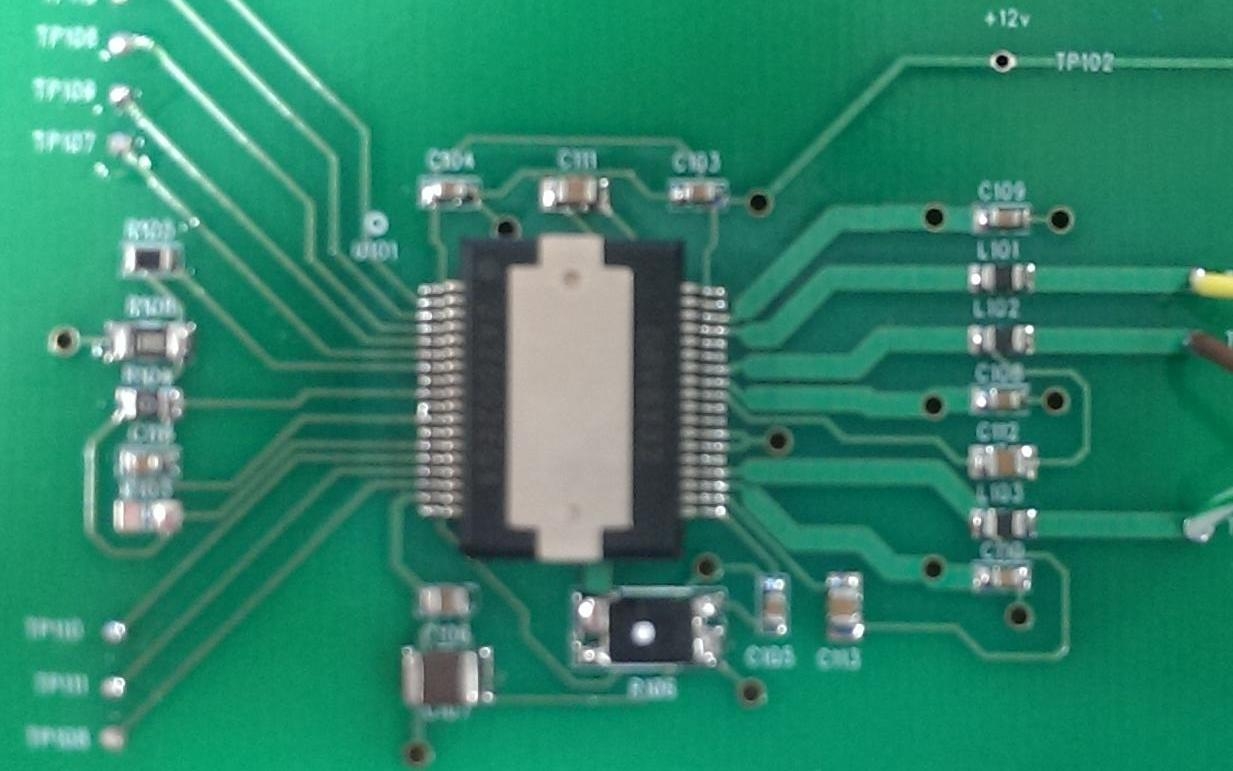
I have a custom PCB based on the design of the DRV8312-C2-Kit (with the 8332) being ran by a TMS320F28335. While my motor runs great unloaded at a constat speed, I keep shorting the chip while I try to start, stop or change the direction of the motor on the fly. Both my PVDD and GVDD supplies current limit, and I measure shorts between a bunch of the pins (bootstrap caps, PVDD to GVDD). I was wondering if this could be due to some back EMF or going over the absolute max ratings maybe (any of the -.3V ones, specifically).

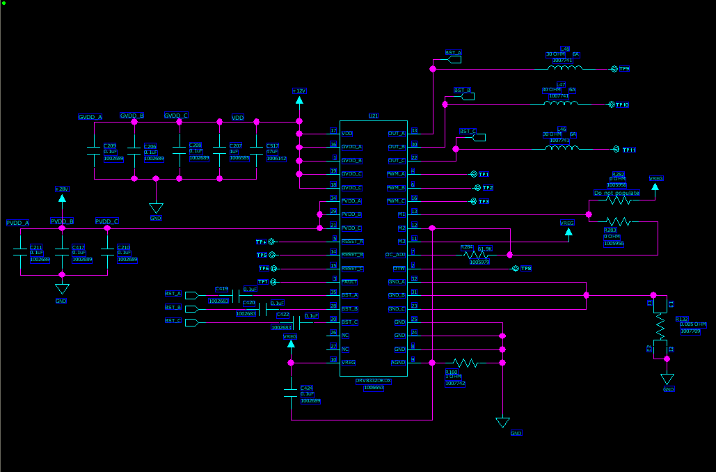
I don't think it's a software issue, as I can run my code on the eval board without any problems. Do you guys happen to know any common causes of this type of failure? Are diodes recommended between the OUT_X and GND_X pins to maybe help with any negative voltage spikes? I can share my schematic, but I have done some mods on the board, so it would have to be fixed up first.

Any help is appreciated.

Thanks,

  • Hale,

    Is it highly possibly that it is a layout issue. If it is possible to get an updated schematic/layout we could start the debug there.

  • Nick,

    See the attached schematic of the DRV8332. To ensure it wasn't a layout issue, I did a quick turn proto-board, following the recommended layout in the datasheet. I did see some improvement, but the chip is still failing while I try to increase the speed when lifting 5-7lbs through a 25-1 gear ratio. My supply is current limiting the chip to 4.5A, so I wouldn't think that would be the cause of the failure.


    Thanks,

  • Hi Hale,

    I am not seeing the schematic, and can you also attach a snapshot of the layout around the DRV device.

  • Sorry, I edited my previous post to include the schematic. See snapshot below (sorry for the blurriness):

    Also see the DRV8332 input and output wave forms:

    Inputs:

    Yellow - PWM A

    Green - Reset A

    Purple - PWM B

    Pink - Reset B

    Outputs:

    Yellow - PWM A

    Green - PWM B

    Purple - PWM C

    Thanks,

  • Hale, I understand your boards develop a short between PWR and GND after trying to use them.  Can you isolate which component is shorting?  Be sure to first disconnect your external power supply from the board, then measure the short at the power terminals, verify it's present with both probe polarities (so you know it's not a diode), and remove components until it goes away.

    What is your PVDD voltage, and the voltage rating of bypass capacitors?  It is good practice to use bypass caps that are rated 2-2.5x the rail voltage.

    In the blurry image, it almost looks like we can see a solder short between two pins on the left!  I suspect that's not the main issue though.

    Best regards,
    RE

  • RE, after measuring, the only 3 caps that were NOT shorted were V_REG, BST_A and BST_C. The shorts on all of the remaining caps disappeared once the DRV8332 was removed.

    PVDD is at 28V, with the BST caps rated at 100V and all other bypass caps at 50V (I will bump them up to 100V to be safe).

    The short you see is intentional, it is between pins 10 & 11 (V_REG to M3).

    The chip usually gets damaged while trying to increase the duty cycle, do you believe it could be due to ground bounce? I am quickly accelerating the motor and then dead stopping it a few seconds later. Any other ideas?

    Thanks,

  • It does sound like an absolute max rating is getting exceeded, for the DRV8832 to be damaged.  I'll continue investigating.

    Best regards,
    RE

  • Hale,

    When you say increase the duty cycle is this in steps (1%, 5%, 10%). Instantaneous changes can be very harsh on a BLDC system. I would not advise a dead stop.

    Also,

    I do not see a GND plane on the top layer. Is this on the bottom layer? What does it look like?

  • Hi Hale,

    I noted that the bulk capacitor for PVDD is missing on your schematic and board. On the DRV8312-C2-KIT schematic, there are 2 470uF bulk caps at the PVDDIN terminals (see the upper left side of page 3 of the schematic). Without a large bulk capacitor, the problem that you are seeing is very possible.

    Please add a bulk cap of at least 470uF across the PVDD to GND on your board. If that does not correct the problem, can you send the layout and current schematic in its native program. We have access to many viewers.

    Thanks.

  • Nick,

    Yes, I may be changing it a little too instantaneously and therefore possibly exceeding some max rating. Let me replace the chip and try changing it in smaller steps, I'll let you know how it behaves.

    Also, here is the back of my proto-board; it is one ground plane with the +28V (thick trace) and +12V (thin trace).

    Thanks,

  • Rick,

    I added a 680uF 63V cap to the PVDD input. I am also accelerating and decelerating by ~10% duty cycle while starting and stopping. So far it seems to behaving better. I have two questions though:

    1) My final board will have EMI, lightning and surge protection, would this bulk capacitance still be necessary?

    2) It seems that I'm able to reach a higher top speed and handle slightly more torque, but while I make the duty cycle ~90%, I only see my supply pulling <2A of current. I need to achieve a higher speed and handle lifting a few more pounds still, but I can't seem to make it happen. Is this due to the PVDD voltage being too low and thus limiting my speed? Or how else can I supply more current to handle a larger load if I'm already nearing the limit on the duty cycle?


    Thanks,

  • Hale,

    You will still need the bulk capacitor after adding the protection, unless part of the protection circuit includes a bulk capacitor after the EMI inductor. The bulk capacitor is there to provide instantenous current that cannot be supplied immediately from the power supply.

    The speed of the motor may be limited by one of two items; the cycle by cycle current limit or the BEMF. Can you provide a few motor details?

    What are the motor specifications; manufacturer, model, resistance, inductance, number of poles, Kv and Ke?
    What is the speed of the motor at 90%?
    Please confirm the voltage the motor is running.

    To determine if it is cycle by cycle current limit or BEMF, the easiest method is to increase PVDD by a couple of volts assuming you are not exceeding the motor specifications. Raise the PWM duty cycle until the motor speed stops increasing. If the motor speed stops increasing at a lower duty cycle than the previous VDD, it is probably the cycle by cycle current limit.  Modify the OC_adj resistor to increase the current limit. If the motor speed stops increasing at a higher duty cycle, you can increase PVDD again.

    Another method of checking this is comparing the input PWM duty cycle to the output PWM duty cycle. If these don't match, the cycle by cycle current limit is limiting your max speed.

  • Rick,

    Thank you for all the information, I appreciate your help. The motor is a Portescap B0912-050A.

    I will try out that test, but I did find what I think to be a major cause of the lack of speed. The ground connection from my DRV proto board to my processor (supplying the PWM signals) was over a long wire with clips. Since these two are supplied from two isolated PSUs, I soldered on a much shorter and higher gauge wire between them, and the results are much better. If the two ground potentials were that different, I guess the DRV could have been missing some of the PWM pulses? Well, I seem to be getting closer to the performance I need!

    Thanks,

  • Rick,

    Can you provide any information on the minimum amount of bulk capacitance needed for the DRV8332 in an application with worst-case 4A continuous? I understand it may be under the recommended value and that it may also affect performance; I ask because my product is for an aerospace application and I'm trying to stay away from tantalum and aluminum type capacitors. It's pretty difficult to find high capacitance/voltage ratings for ceramic types that have a reasonable footprint size.

    Thanks,

  • Hale,

    The size depends on a number of factors, primarily how far away the power supply is from the board and how much change is acceptable in PVDD. Too small and you will start seeing large voltage spikes again, the motor may not run at high duty cycles, or may not start up.

    The general rule used here is a minimum of 2uF/W. Most of our boards cover a broad range of applications so the capacitors are often larger than needed in a specific application. For your application, that works out to 2 * 28V * 4A = 224 uF. I suggest that you use an 220uF aluminum on your evaluation board. Examine the positive and negative spikes on PVDD as you start and stop your motor. Adjust as needed. In

    I understand your desire to stay away from tantulum and aluminum capacitors. Best of  luck finding a ceramic equivalent with a reasonable footprint and cost. 

  • Rick,

    Thanks for your help. I did start to see the performance degrading right around 75uF. I'm going to go with two (very large and pricy) 100uF ceramic caps.

    Thanks,

  • Hello Hale,

    I am starting designing using the same IC. I will require your help. So finally what is the status of your design? Is it working ok?

    Also you have not used any heat sink...or may be you have removed and posted the picture.