This thread has been locked.

If you have a related question, please click the "Ask a related question" button in the top right corner. The newly created question will be automatically linked to this question.

Questions on DRV8412-C2-KIT

Other Parts Discussed in Thread: CONTROLSUITE, DRV8412

We recently purchased a DRV8412-C2-KIT, it's been setup and the step motor seems rotate fine. But we found that whenever we enable the step motor on the GUI, the motor start to have some high frequency noise (I can heard the noise with my ears). We also later on find out that the motor also produce noise and couple to my measurement, and the noise is very bad (electric magnetic noise?). I want to see if this is the malfunction of the step motor, or if this is due to some wrong setting on the software or hardware.

Also, we want to be able to control the step motor in a constant speed, but the GUI can only allow max. 800 steps/sec in speed mode. and I can get to much higher speed in index mode, but it's less convenience. Is there a software update that can provide a large max speed in speed mode?

  • Hi Weibin,

    Can you provide more details? Please provide the exact procedure to produce the noise. We would like to duplicate it here.

    I will have to look into your question regarding a larger max speed in speed mode.

    Thank you.

  • Rick,

    I only connect the controller and motor following on the manual, install the software. After I establish the connection between the motor and computer, I click the enable button on the step motor tab, I can instantly hear the high frequency noise the motor produce. Every time I uncheck the button, the noise is gone. The motor is not even rotating at that point. Other than that, the motor runs fine. I don't know if the noise source is the same, but I probe the stage that mount the motor, I can see  large noise from my oscilloscope. The noise exist whenever i enable the motor, regardless it's rotating or not. The sound seems like it's from the motor, not the controller, but the cable is quite short, so the controller and motor are quite close, and I am not 100% sure about this. Again, I am talking about both noise I can hear with a high frequency pitch, and also electrical noise I can observe from my measurement. I wonder if I need to shield the motor to prevent that.

    I have an IC give me 2.5V output, but when I enable the motor, the signal jump up and down, p-p can get to tens of mV, and the resolution of that chip is typically at at most 8mV. When I disable the motor, in the software, the noise drop back down.

    Weibin

  • Hi Weibin,

    I understand it is both electrical and acoustic, and when the motor is not rotating. Thank you for the procedure to reproduce the noise you hear. We should have an update in a few days.

  • Hi Weibin,

    The GUI PWM frequency is 10kHz, in the audible range. I have confirmed this on our bench. I believe the stepper code will allow you to change the PWM frequency up to 60kHz.

    To increase the speed in speed mode, have you tried reducing the microsteps/step setting? If this does not work, you may have to move to the stepper code in controlSUITE.

  • Ricky,

    How do we change the PWM frequency in the GUI? I can see in the setting of step motor, the Ki has a unit (Hz), is that what you talked about?

    Please give me a more detailed instruction on how to change the PWM frequency. I don't know about the other development tool, I am only using the control GUI come with the software, which only allow me to move some knobs and change a few setting. I don't have time to change any coding now.

    Weibin

  • Weibin,

    I will have to do some research on this. Will provide an answer soon.

  • Also, I don't think changing the frequency will produce less noise anyway, i may not hear it, but the electrical/magnetic noise will still be there. I care more about this than the accoustic noise.

    Weibin

  • Weibin,

    I have checked into modifying the GUI. It is not recommended due to the GUI communicating with memory directly in the C2000. If the memory locations of variables do not match after compilation, the code will not work.

    Please refer to post http://e2e.ti.com/support/microcontrollers/c2000/f/171/p/254139/895255.aspx#895255 for more information.

    Increasing the duty cycle may help with some of the electrical noise. The current ripple will be reduced which may help.

    If you provide your requirements, we can suggest another EVM that may better suit your needs. We have several DRV8x EVMs showcasing devices that have all the control logic integrated in the device. A much simpler microcontroller can be used with these devices.

    Thank you.

  • Ricky,

    I have hard time to completely understand what you said in the last post. So let me rephase it  and hope we don't miscommunicate here. Also, that's why I prefer a phone support, this kind of forum support suck big time, it waste me more than a week, still don't get my answer/solution to the problem.

    1) Based on your post, the electrical noise can be reduced by changing the PWM frequency (i.e. increase the duty cycle), Right?

    2) However, you cannot provide a way for me to alter the PWM frequency in the GUI. (Comment: which make the answer/solution pointless as you are telling me a way to solve the issue, but then telling me I can not do it in that way due to the limit of the GUI.), I hope I am understanding correctly here.

    3) I have installed control suit. Previously, I have no clue what you are talking about in terms of code compiling. I still have not much clue now, but it seems that client can compile their own code or modify the code then ran the modify version of the code. In this case,  can you provide a modified version of such GUI to enable PWM frequency change? (Maybe you already answer the question, but I don't know if this is what you mean in the last post).

    Buying a new hardware is not much of option for me, I have limited time now. For the code compiling and software installation, please provide details for me to follow, I am completely new to this controlsuit software platform.

    Thanks,

    Weibin

  • Weiben

    1. yes, 10 KHz is audible for humans. you need to go above 20 KHz for inaudile (and even above 26 KHz for young ears)

    2. The GUI is not meant to change all available software configurations. It is NOT an embedded design tool, it is a demonstration tool that lets you instrument the embedded software that we have written to run on the processor and control a power stage.  There is no situation in which we ever expect someone to simple take this example and try to use it as a product!  In the cae of the PWM frequency, this is not somethign that can be instrumented. This must be changed in the CCS project source code, recompiled, and then run on the MCU.  One of the negatives in using the Crosshairs Embedded GUI is that the .exe is tied to memory map of the compiled .out when we "deploy" the GUI.  That means that if you create, load, and run a new binary it often won't work with the GUI .exe (it only will work properly if all variables are in the exact same memory location).  Part of this is a technical limitation of the tool, and part is because Crosshairs Embedded wants to sell you a license to their tool so that you CAN deploy your own custom GUI.  They let us create GUIs as a way to market their tool.  We no longer have this business relationship with them as TI now has their own GUI creation tool - GUI Composer - inside CCS.

    3. If you don't know what code compiling is I have to question the scope of your project.  The intent from TI motor control using an MCU + a DRV power stage chips is that you will take our example project software, modify for your needs (including making changes for your own custom HW and host / user interface / communication SW), test, and create a product.  The GUI we provide is NOT part of your product.  If you want to make a GUI that is part of your product you can purchase tooling from Crosshairs Embedded (what we used to create the DRV8412 GUI several years ago) or through GUI Composer which is included in our Code Composer Studio development environment.

    I think we are have a miscommunication on expectations....and I apologize for that.


  • Thank for your answer, Chris.

    I have to agree, to some degree, we purchase this kits that doesn't not perfectly match out application. This kits is powerful and can potentially provide a very versatile solution on our setup (Note that we are not developing a product, we are just using it as an experimental setup to calibrate our product, and this will never become a product that we can sell in my opinion. But I am still frustrated on the outcome at this point. How can this controller and motor be such noisy (both electrically and audibly?) with the step motor with default setting in the software unit, and TI cannot provide a solution for me? I called the step motor manufacture, but they said this have something to do with the communication/control scheme between the driver (controller) and the motor, not the motor itself. If you are selling a a motor or a controller, that's fine. But it come as a combo kits, and at least some basic engineering work should have been carried out for noise and electromegnetic intererence before it come to market right?

    I hope this is just a single accident that I happen to be unlucky to get a malfunction step motor. I doubt it based on what i see. I connect to the DC motor come with the kit, I can still measure the noise from a stainless steel stage that doesn't even connect to the motor. It seems both the motor and the control kit both produce the noise and got picked up but a large metal piece. the frequency is exactly 10kHz. Did you guys have any scheme to shield the motor housing? to prevent those inteference? Anyway to shield your control board, too?

    Weibin

  • Hi Weibin,

    I am sorry for the issues you are having. Electrical noise and electric magnetic noise are unfortunate side effects of driving an electric motor. Motor drive systems are subject to a large amount of this noise as well as systems in close proximity. Another name for this phenomenon is called EMI and there are a variety of ways to deal with this. For some customers it is a don't care and for others it is a critical factor. It is difficult to plan for all scenarios in our designs and our EVMs are just meant to give the customer a basic demonstration of the part and allow them to create their own solution.

    As has been mentioned, dealing with audible noise is a simple matter of raising the base PWM frequency. The other issues are more complicated and there are no ways to eliminate it completely in the imperfect world, only manage.

    In this thread there was a discussion on managing EMI. I am sure there are many threads in the forum discussing similar topics as well.

    http://e2e.ti.com/support/applications/motor_drivers/f/38/t/284878.aspx

    For more basic noise, most motor systems simply have to just reach an acceptable level of tolerance. It really depends how much effort you are willing to spend on the issue.

    One way is to provide electrical isolation for everything that is interfacing to an external circuit. Or as you mentioned if the coupling noise is an issue, shielding for the motor.


    To clarify, what issues are you experiencing besides the audible noise? Keep in mind you will always see noise on lines in a motor control system and many other systems. Most have been designed to tolerate an certain level of it. To answer your last question, we do not have any specific shielding schemes as this is not an ideal solution for most customers.


  • Nick,

    We finally get to the point. In the link you provide it says following:

    1. For EMI purposes a snubber consisting of a resistor in series with a cap can be placed in parallel with each of the stepper windings. Resistor value can be 10 ohms and capacitor about 470 pf or 1000 pf. At the same time, 470 pf ceramic caps can be placed from each output to GND. We have heard good results about this ombination.

    How do we define stepper windings here? I can see 8 wires coming out from the step motor, and each OUTPUT on the control board, A, B, C and D connect to two wires. Does this pair of wire counted as one stepper windings?

    Second,  If the GUI cannot change the PWM frequency, what other option we have? Please provide a little more details, as I have not used any of your software development tool. I did install the controlSuit recently but have not had time to play with it yet.

    Weibin

  • Also, farther down in the post you can see a recommendation for ferrite beads which have been seen to give even better results.

    I am confused here though. This kit is designed to drive a bipolar stepper motor which should have 4 wires. The four wires will be for two windings (Hi and Low side on each). You will usually see these referred to as A+/A- and B+/B-. If this is a bipolar stepper you will have to refer to the motor data sheet to determine the correct wires as it varies from motor to motor.

    If you motor is as previously stated the connections to the EVM (and as shown in the DRV8412 datasheet) would be:

    A+ to OUTA

    A- to OUTB

    B+ to OUTC

    B- to OUTD

    As Chris/Rick were saying to change the PWM frequency you will either have to modify the existing software (GUI) & firmware (C2000) combination or write your own firmware/software. ControlSUITE contains the projects we release with the kits if you wish to take a look at them. There is a subfolder in development kits for the DRV8412 kit. To modify the firmware you will need some sort of IDE, the main one being Code Composer Studio. If you are unfamiliar with GUI and firmware development this will require some work and learning. I would start by understanding the example projects first. There are documents in ControlSUITE you can read for information as well as the firmware source code.

    Many customers we sell to have their own code that they run or design projects based off of the EVM code examples.

  • Nick,

    The step motor has 8 wires, and 4 pairs, each pairs connect to OUTA, B, C, D. And the manual shows the same. I am not sure you are talking about other kits. But the kits we ordered has a step motor come with 8 wires, and the manual indicate so. all this wires are color coded, and I connect to the board based on the instruction from the manual.

    Weibin

  • Weibin,

    Can I see this manual and data sheet for this motor? Does this motor have 4 windings then? As I mentioned, standard bipolar stepper motors have 2 pairs (2 windings), I am staring at one as I type this.

    There is information on our different kits in controlSUITE. Find the DRV8412-C2-KIT folder in development kits for information specific to your EVM.

  • 0160.QSG-DRV8412-C2-KIT-GUI.pdf.

    I cannot find it on the webpage, and don't want to waste my time to dig into that. I attached the pdf file i have in this post, let me know if you cannot see it.

    Weibin

  • Thanks for the file Weibin, this clarifys some things.

    The board you have is actually one revision back of the latest board I believe. We no longer ship motors with the new revision. In general Bipolar steppers have 4 wires, one wire on each side of the winding.

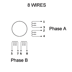
    There are some variations on this, which includes the one you have. See the picture attached.

    In a 4 wire stepper motor you just have connections to 1,4,5, and 8. The middle two pins are tied together internally.

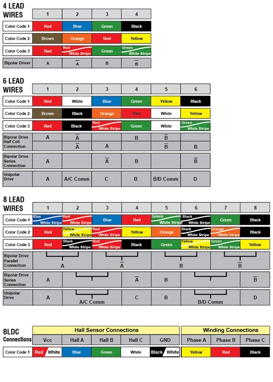
    So back to your original question. 1 winding is between pins 1 and 4, the other is between 5 and 8.

    Or from the board, OUTA and OUTB drive one winding, OUTC and OUTD drive the other. You can refer to the image below for more details on the various configurations.