This thread has been locked.

If you have a related question, please click the "Ask a related question" button in the top right corner. The newly created question will be automatically linked to this question.

Temperature issues on stpper motor with DRV8811

Other Parts Discussed in Thread: DRV8811

Hi,


I'm using the DRV8811 for driving a stepper motor;

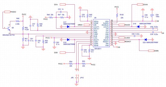
I'm using the following circuit:


when PWDDO on the base of Q5 is 0V, VREF on U9 is 0.958V and Ichop is 0.399A - in this condition, the motor is stopped (holding condition);

when PWDDO on the base of Q5 is 5V, VREF on U9 is 1.949V and Ichop is 0.812A - in this condition, the motor is moving (running condition) in 1/4 step;

the motor's maximum current is 1A;

VM=24V;

PVCC=5V;

the circuit works fine but the motor's mean temperature is really high: 50°C;

this circuit is designed to replace an old circuit that use Toshiba TA8435;

the old circuit drive the motor with the same current limit in the same conditions: holding condition:0.5A, running condition @1/4 step:0.8A but, with the old circuit, the stepper motor mean temperature is smaller: 39.8°C; 

1) which can be the cause of this behavior?

2) the increase in temperature may be due to the chopper frequency?

3) What happens if the chopper frequency is too high?

4) this circuit, must drive different motor with different characteristics; there is a rule of thumb to determine a good value for C62-R52 and C57-R49?


thanks in advance


Fabrizio

  • Hi Fabrizio,

    Can you provide some additional information?

    How are you determining the mean temperature? Can you separate the temperatures to determine if the holding temp, or running temp is higher than expected?

    It may be that current regulation has been lost during holding condition. One quick method to check this is to change from mixed decay to fast decay. This will cause more current ripple but should allow you to determine if the holding condition is causing the temperature to rise. If you have access to a current probe, please examine the current during holding to determine if the device is regulating properly.

    The chopper frequency should not be causing this behavior. Many of the devices are designed to run between 40kHz and 60kHz.

  • Thank you very much for your quick answer,

    the mean temperature is measured with an NTC connected to a DDM that can continously acquire data;

    the time that the motor remain in the holding position, is considerably larger than the running condition so I can state that the temperature rise is due to the holding condition;

    I don't have current probe at the moment, I have ordered two current proble for my scope but there is a long delivery time;

    1) what I can try right now?

    2) the chopper frequency period is composed of t off and ton; t off is fixed t on depends on the motor; how can optimize the chopper frequency for a family of motor?


    thanks again

  • Hi Fabrizio,

    Assuming your power supply has a current readout, read the holding condition with mixed decay and fast decay. If the current is regulated properly, mixed decay should read less than fast decay. If fast decay is reading less than mixed decay, current regulation has probably been lost in one winding. Please let me know the results.

    Regarding the optimized chopper frequency, we will have to research this. We will update soon.