


Hello motor drivers Gurus,
I have a problem hard to tackle with my drv8312 and I was wondering if you had some inputs to help me out.
So I am working with a 24V motor 3Ph with block commutated control, the nominal speed of the motor is about 2600 elec. revolution / sec. The nominal current consumption is less than 1A without load . The driver circuit is inspired from the DRV8312-KIT.
In normal operation :
At full speed, I am using about 0.7A and motor and driver are cool.I think my PI controllers are correctly setup because it behaves correctly to abrupt load change and wide variation of the control input.
The b-emf (in blue) seems OK from my little experience working with these drivers :
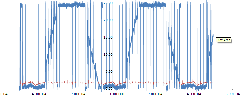
The current waveform seems OK to me as well.
When the problem occurs (rarely) :
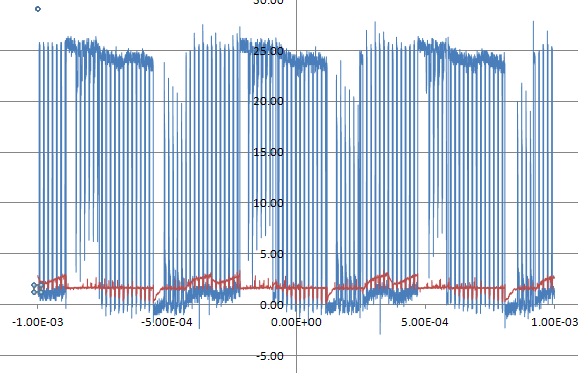
Rarely it occurs 10 seconds after starting up the motor, I get an over-current from the driver. The motor doesn't make any different noticeable noise. The motor speed ramps up normally but the current consumption is "huge". It can go up to 3A continuous before the driver shuts down. Here is a capture before the motor shuts down :
Different possibilities explored :
1/ I have checked the way I start-up the motor. I manually generate a sequence of pulse with fixed duty cycle until I complete one electrical revolution, then I toggle to fully PID controlled scheme. I have tried different pulse ramp-up profile but the problem persists. I have also tried to delay the toggling to full PID controller without success.
2/ Investigate the PI for current controller. I have tried several configurations without success. Before it crashes, I have noticed that my integral term is high... explaining the higher current consumption.
Any thoughts are welcome, let me know if you need any extra information to have a better understand of the problem. Thank you.

