This thread has been locked.

If you have a related question, please click the "Ask a related question" button in the top right corner. The newly created question will be automatically linked to this question.

Last check on my driver board before I send it up to fab.

Other Parts Discussed in Thread: MSP430G2553, DRV8840

hey guys, I am working on a project, and would like someone with more motor experience to look over the board real quick before I send it off to be made. just to make sure i didn't miss anything silly.

the driver is a DRV8840 the micro-controller will be a MSP430G2553

the motor is 18V DC Brushed and draws around 4.5 amps

because of the small board size (40mm square), I plan on mounting a heat sink directly to the back of the board

I studied the files for the evaluation module and I think I emulated it close enough.

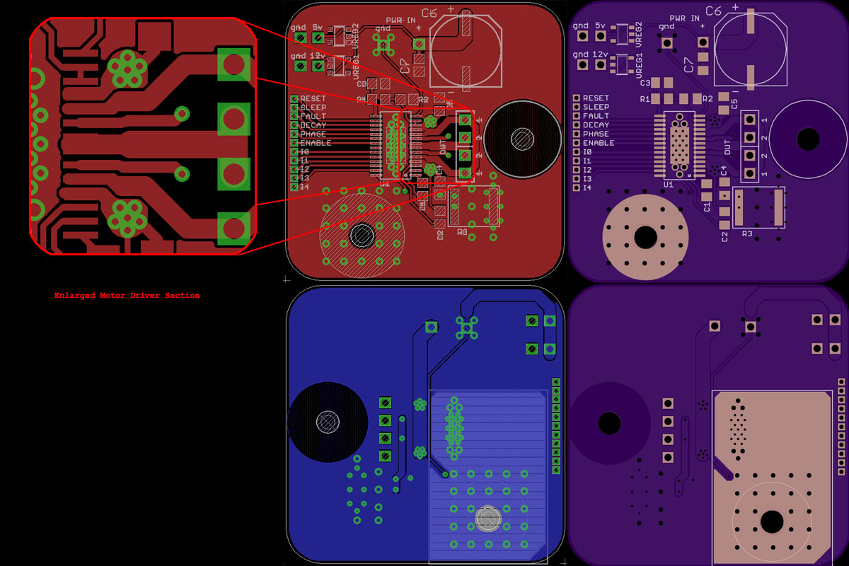
I'm not a big fan of the pin layout on the chip having the pins split apart and having to connect them together in a small space is difficult with the high amperage traces and what not.

JWoodrell_Motor_Driver.zip
  • Joseph,

    I am not able to open schematic in your zip file. Please attached pdf version of  schematic for easy access.

    Best Regards

    Milan-Motor Application Team

  • here is the schematic, and the two layers saved

    the other files were from Eagle.

    Thank you for taking a look at it.

    PDF_JWoodrell_Motor_Driver.pdf
  • Thank you for looking over it, if there arent any silly things, I will send it up tonight.  I am just getting started in working with motors and amperages like this on a PCB.

  • Hi Joseph,

    Glad to here you are getting to motors. As you seem to realize it is important to be considerate when routing high current traces and dealing with the thermal dissaption. 

    • There is a recommended land pattern for the vias in the PowerPad in the datasheet. I would recommend following this for best thermal dissapation. You can then add additional vias around the device as you see fit.
    • Are there two separate GND traces in this design? I would recommend connecting all GND traces to the same copper. (there are many arguements for an against seperate GND planes/traces but we have seen that a single unified GND plane gives the best performance.
    • I would possibly increase the copper and vias to the sense resistor. Remember this trace will handle the combined 4A.
    • The circle cutout on the right seems to be reducing the GND return path to the supply from the sense resistor. May want to make this path slightly larger.
    • I would also recommend stitching the GND planes together on the entire board
    • Opening up the top copper plane for the PowerPAD will also help with thermal dissaption. This will be a concern in a design this size. Going to need to dissapte at least 5.265W from the FETs (will increase as temp increases) and 2W from the sense resistor
  • thank you for the input Nicholas.

    here is what I ended up with after working in your feedback.   If you were interested,

    I should get it back in a week and a half from OSH park and I'll see how well it works.

    switched the thermal via pattern for the DRV over to the 3 x 7 pattern in the datasheet (omitting one for trace routing)

    bumped up the trace width to the sense resistor, as well as the number of vias

    the separate ground traces  were towards star grounding for the power out to the micro controller (5V regulator)

    the circular cutout was where the board mounted with a 4-40 screw, but there is no harm in extending the ground plane into that area as well.

    stitched as much of the top and bottom ground plane together.

    micro_Motor_Driver_fab.pdf