This thread has been locked.

If you have a related question, please click the "Ask a related question" button in the top right corner. The newly created question will be automatically linked to this question.

DRV8811: question about Ichop value

Other Parts Discussed in Thread: DRV8811

Hi,

I'm testing the following circuit:


when PWDCA is 0V, VREF=1.25V and Ichop=0.52A

when PWDCA is 5V, VREF=1.98V and Ichop=0.83A

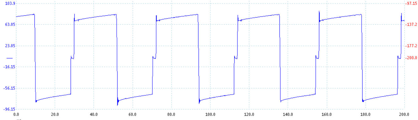
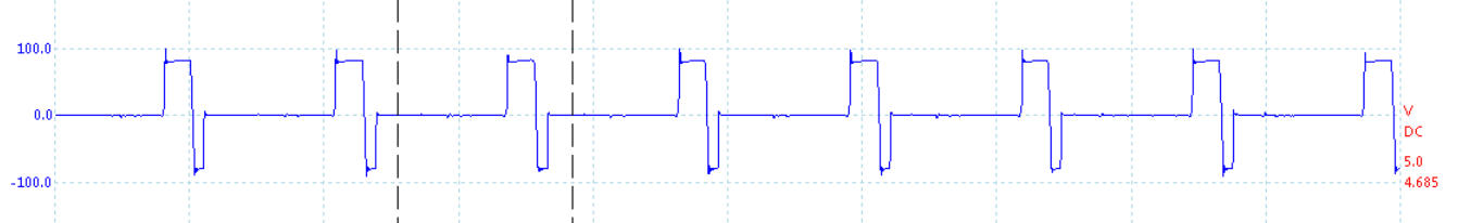
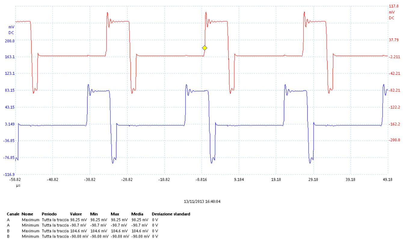
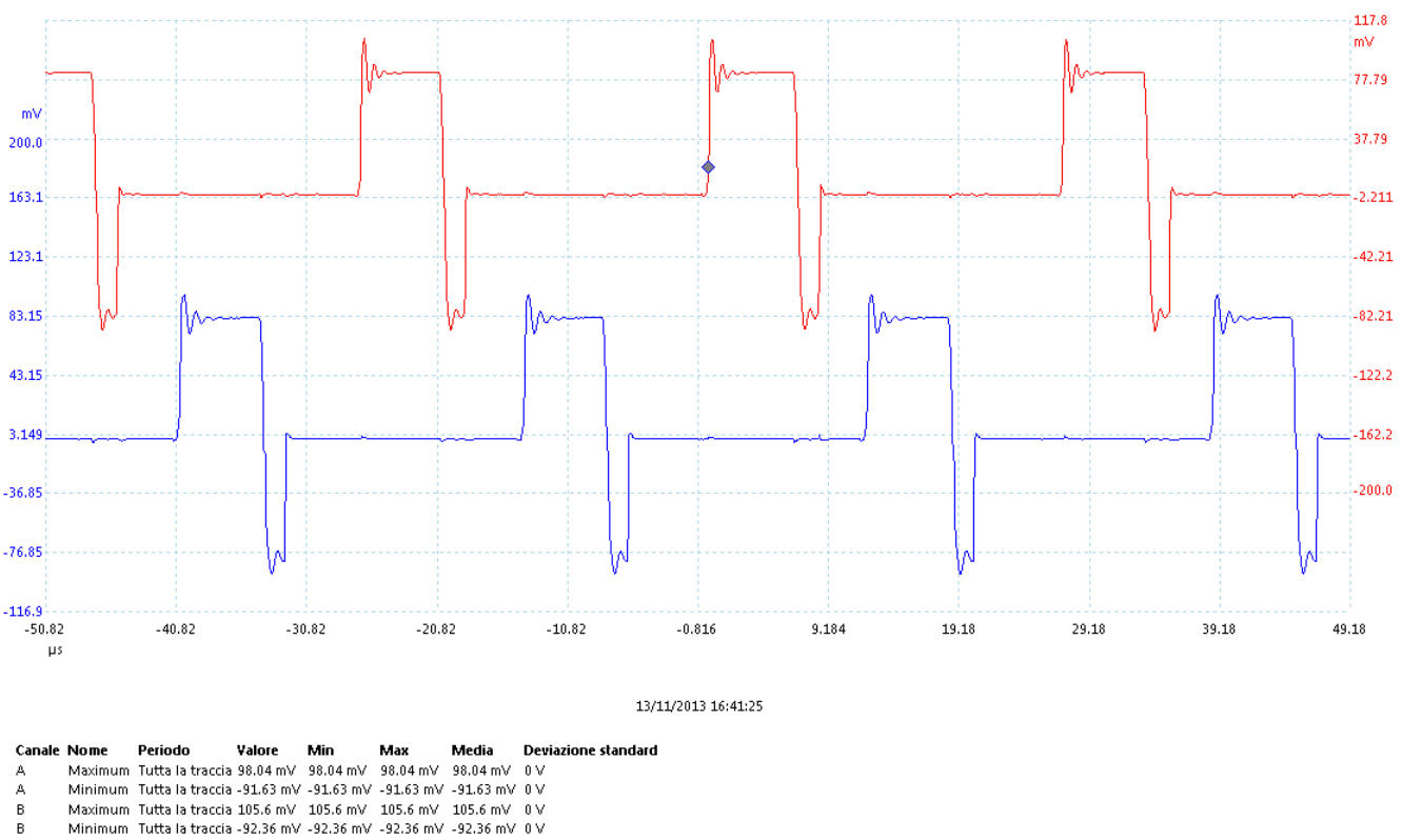
the following picture shows the voltage waves form on pin 1 (red trace) and on pin 6 (blue trace) of U1 when PWDCA is 5V, VREF=1.98V and Ichop=0.83A;

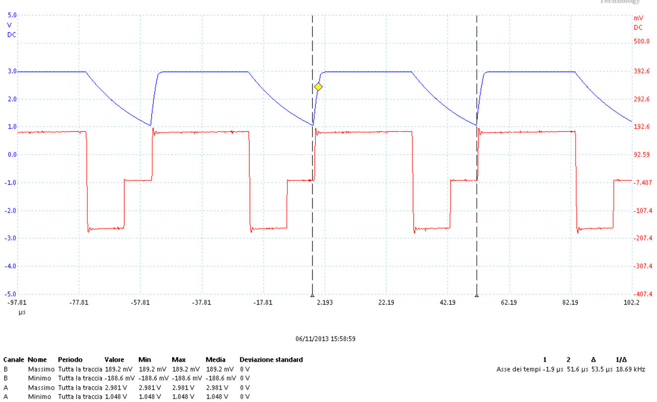
as it can be seen, the peak value of the voltage on pin 1 is 189.2 mV; the voltage drop across R23=0.3 ohm; with this value, Ichop seems to be:

Ichop=(189.2mV)/(0.3ohm)=0.63A and not 0.82 calculated with the formula Ichop=(VREF)/(8xRsense)=(1.98V)/(8x0.3ohm);

is there something wrong in the measurement?

Best regards Fabrizio

  • Fabrizio,

     I am not able to exactly pin-point the cause of such error (around 23%) in measurement. I could have justified over-all accumulated error of 5 to 10% but this just way high. We would need to investigate this in detail to find exactly what going on. The other thing which bothering me, is that current waveform is not symmetrical in positive and negative half, positive half is more and negative half peak is divided into two halfs. Typically these two sections should be symmetrical in Full-step mode.  

     In order to investigate these issue, I would request you to:

    1. Capture the same waveform with Vref input in both winding This would confirm if theoretically calculated Vref is actually applied to IC.
    2. Repeat this test in couple of other units, to get the repeatability of above measurement.

    Also please let me know if you are intending to operate in full-step or some other mode, I could not figure out it from schematic because JP5 and JP6 positions are not mentioned.

     Best Regards

    Milan-Motor Application Team

  • Hi Milan,

    after all, thank you very much for your support;

    the motor operate at 1/8 step;

    For answer to 1. and 2. I need more time; next week you will have the picture...

    Best Regards

  • Hi Milan,

    i think that the asymmetry in the Rsense voltage wave form is due to the tFD of the mixed decay mode (see DRV8811 datasheet, page 10);


    the following pictures show this behavior:


    Vdecay=1.181V, VCC=5V, R=12.4K, C=1.5nF - the DRV8811 remain in fast decay mode for tFD=17.3 micro seconds


    the wave form is much more symmetric;


    Vdecay=2.83V, VCC=5V, R=12.4K, C=1.5nF - the DRV8811 remain in fast decay mode for tFD=1.09 micro seconds

    the wave form lost the symmetry;


    is that correct??


    Best regards

  • Fabrizio,

     You are absolutely right. The asymmetry is due to Tfd, time for which device remains in fast decay ode.  If  Tfd is higher  asymmetry would be lesser.

     Ok, so now let’s get back to our main agenda about peak current Ichop value. Please get the results as discussed.

     Best Regards

    Milan-Motor Application Team

  • Hi Milan,

    I'm back with some news;

    the following picture show the last version of the schematic:

    when PWDCU is 0V, VREF=0.958V and Ichop=0.399A

    when PWDCU is 5V, VREF=1.949V and Ichop=0.812A

    I have tested two different boards (with the same components configuration) with the same motor in order to test the repeatability of the problem;

    A) PWDCU is 0V, VREF=0.958V and Ichop=0.399A

    RESULTS OF FIRST BOARD:

    the following picture shows the voltage waves form on R23 and R31:

    as it can be seen, the two wave form are quite similar so we can confirm that VREF is correct;

    the maximum peak value is 104.6 mV; with this value and R23=R31=0.3 ohm, Ichop seems to be:

    Ichop=(104.6mV)/(0.3ohm)=0.349A which is quite similar to the value calculated with the formula Ichop=(VREF)/(8xRsense)=(0.958V)/(8x0.3ohm)=0.399A;


    RESULTS OF SECOND BOARD:

    the following picture shows the voltage waves form on R23 and R31:

    as it can be seen, the two wave form are quite similar so we can confirm that VREF is correct;

    the maximum peak value is 105.6 mV; with this value and R23=R31=0.3 ohm, Ichop seems to be:

    Ichop=(105.6mV)/(0.3ohm)=0.352A which is quite similar to the value calculated with the formula Ichop=(VREF)/(8xRsense)=(0.958V)/(8x0.3ohm)=0.399A;

    this measurement confirm the repeatability of the two boards that give the same results with the same stepper motor and show that, when PWDCU is 0V the theoretical value and the measured value are quite similar;

    B) PWDCU is 5V, VREF=1.949V and Ichop=0.812A

    RESULTS OF FIRST BOARD:

    the following picture shows the voltage waves form on R23 and R31:

    as it can be seen, the two wave form are quite similar so we can confirm that VREF is correct;

    the maximum peak value is 193.3 mV; with this value and R23=R31=0.3 ohm, Ichop seems to be:

    Ichop=(193.3mV)/(0.3ohm)=0.644A and not 0.812 calculated with the formula Ichop=(VREF)/(8xRsense)=(1.949V)/(8x0.3ohm);


    RESULTS OF SECOND BOARD:

    the following picture shows the voltage waves form on R23 and R31:

    as it can be seen, the two wave form are quite similar so we can confirm that VREF is correct;

    the maximum peak value is 197.4 mV; with this value and R23=R31=0.3 ohm, Ichop seems to be:

    Ichop=(197.4mV)/(0.3ohm)=0.658A and not 0.812 calculated with the formula Ichop=(VREF)/(8xRsense)=(1.949V)/(8x0.3ohm);

    this measurement confirm the repeatability of the two boards that give the same results with the same stepper motor. When PWDCU is 5V, the problem appears and still persists on two different board: I expect a peak value greater than 0.8A and the voltage on Rsense show a current's peak value 17.75% lower (0.658A);


    is that measurement correct?

    why the Imax value seems to be lower?

    Best regards

    Fabrizio


  • Fabrizio,

     Thanks for repeating the experiment on two different boards. It’s good to observe that both the boards are showing the similar trends.

    As I suggested earlier, please actually measure the voltage at VRef pin instead of theoretically calculating it. Actual value of Vref might be little lesser than the calculated value due to tolerances of R26,R28,R29 and Q3. Now since repeatability is confirmed, you can just take any one of unit and capture the Vref , together with IsenA or B in single plot.

    I think that this should give us hint to find out the lower value of Ichop value.

     Best Regards

    Milan

  • Hi Milan,

    next picture show the voltage wave form on R23 (RsenseA - blue trace) and the wave form on R29 (Vref - red trace):

    the figure show the variation of Rsense voltage and Vref voltage when PWDCU switch from 0V to 5V (step change coming from the microcontroller); as it can be seen:

    a) Vref=0.963V when PWD=0V and the peak current measured is Ichop(PWD=0V)=0.103/0.3=0.343A - theoretical Ichop=0.963/(8*0.3)=0.401 - measured Ichop and theoretical Ichop are quite similar;

    b) Vref=1.982V when PWD=5V and the peak current measured is Ichop(PWD=5V)=0.1896/0.3=0.632A - theoretical Ichop=1.982V/(8*0.3)=0.826 - measured Ichop and theoretical Ichop are considerably different;

    same problem...highly repetitive...

    Milan,let me know if you need more measurement to fix the problem...

    I look forward to your response...thanks in advance

    Best regards

    Fabrizio

  • Fabrizio,

     There are only two things which decide Ichop peak value, Vref and Rsense. Now with your latest measurement  Vref is fixed so let’s divert our attention to Resnse. A small increase in Rsense value can cause big reduction in Ichop peak value. There might be possibility of additional resistance in series with Rsense depending upon layout or where Rense voltage is measured.

     1.If you are measuring the Rsense voltage at its terminal, I would suggest to measure at at IC pin 1and 14.

    2. Please share the layout of your circuit; I would like to review it.

     Best Regards

    Milan-Motor Application Team

  • Hi Milan,

    1. Next week I will measure the Vref directly on the DRV8811 pin

    2. Can you give me your personal mail addres where send the layout?

    Best regards nd have a good weekend...

    Fabrizio

  • Hi Milan,

    I have tryed the following measurements:

    a. Vref on C37 and Vref on pin 8 of U1 --> I have the same value;

    b. Wave form on R23 and wave form on pin 1 of U1 --> I have the same wave form;

    all the measurements is performed with the scope DC and 1Mohm coupled; the measurement configrm that, there is no parasitic resistances on the PCB and on the instruments connections;

    If you need, I can post the wave form of measurements a. and b. but I can assure you that they are copying the measures taken last week;

    I would like to share the layout with you, but i need a mail address were send it...

    I wait for your address...

    Best regards Fabrizio