Because of the holidays, TI E2E™ design support forum responses will be delayed from Dec. 25 through Jan. 2. Thank you for your patience.

This thread has been locked.

If you have a related question, please click the "Ask a related question" button in the top right corner. The newly created question will be automatically linked to this question.

EMI on the ground

Hi 

I have a Variable frequency Drive for 3 phase IM. I took speed feedback from an encoder coupled to the shaft. It works from 24V supply.When i took it to controller, due to noise i get more pulses. Then i probed it to Scope and found that the signal ground is picking noise and the same noise appears on the pulses too. Can anyone suggest me how to reduce this noise.This noise appears only when the VFD is on.

Regards

Goutham 

  • Goutham, could you share a picture of your setup, and your schematic?

    It might improve things to reduce your wire length, and add additional bypass capacitance near the source of the noise.

    Best regards,
    RE

  • Hi 

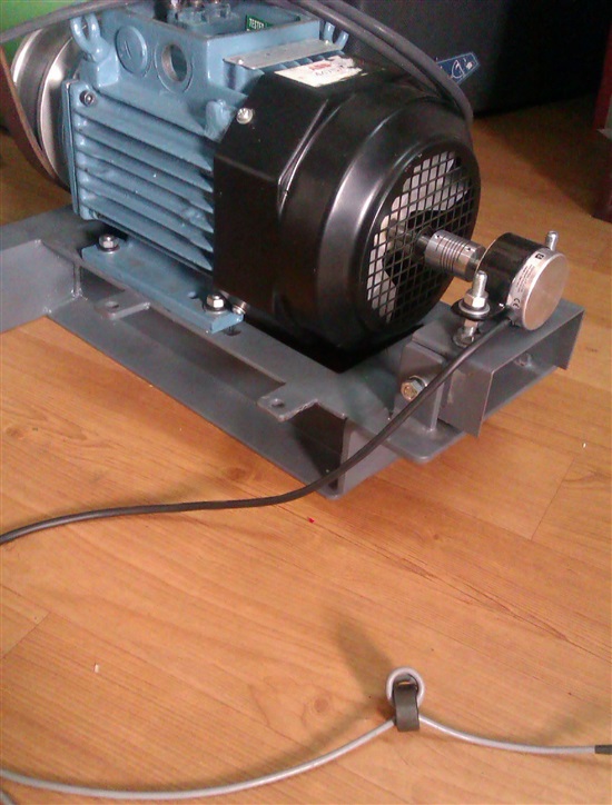
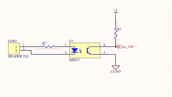
    Below is my motor and encoder setup. Also go through the opto isolator circuit.

    Regards

    Goutham

  • Thanks, the picture is very helpful.  I have a few more questions:

    1. How is the encoder powered, and how many wires go to it?
    2. Is the power to the encoder clean, or does it have the same noise?
    3. Does the encoder's black cable lead to the header in the schematic, off the left side of the picture?
    4. Can you send waveforms before and after the optical isolator?
    5. Can you try a different encoder, to see if that's the source of the problem?

    Best regards,
    RE

  • Hi

    Thanks for your support.

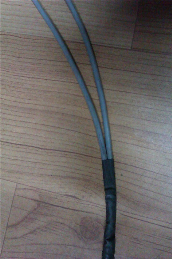
    1. Encoder cable is an 8-core cable(Black). out of that 4 is used. 2 for supply and two for output.

        supply is fed through a twisted pair shielded cable(Grey) and shield is connected to ground. same for output also.

    2. Encoder power is clean and no noise.

    3. The Black cable is encoder output cable, power and output is split in to two 2-core cables, grey cable. 

    4. Waveforms i will try to get it.

    5. Tried on different set up of same type, same problem there too.

    Regards

    Goutham

  • My first reaction is that noise might be getting injected to the encoder through the GND that's connected to the shield.  It's not clear to me how everything is connected, but it sounds like the shield might connect to a shared ground or chassis with the motor.

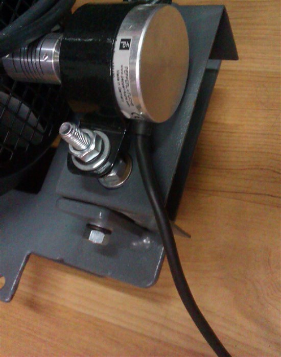
    Looking at the picture, I guess the 4 wires that connect the encoder are all in that black cable leading to the encoder.  You mentioned a gray cable, but I see no gray cable connected to the encoder.  Of the 4 wires, you've got 1 PWR, 1 GND, 2 for signal.  Is that a differential pair?

    For item #2, I guess you measured PWR/GND noise at the end of the black cable.  Of course, the PWR/GND noise could be very different at the encoder.  Is there any way you can measure it at the encoder?  Also, is there any electrical connection between the encoder and motor?

    Best regards,
    RE

  • Hi

    Encoder has a standard shielded cable. It is too short to route to my controller. So i extended it with two wires, one for supply 24v and Gnd next 2 outputs. These two cables have shield and connected to the encoder shield. Finally this shield is connected to the GND. 

    Yes we have two signals A and A-, shall i connect a difference amplifier and check?

  • Thanks for elaborating on that.  I'm still very interested to see waveforms of the signals before & after the optical isolator.

    Best regards,
    RE

  • Hi

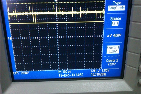
    i checked my supply it also has noise when the motor runs. 

    I attached the snapshot. Once the encoder set-up is ready i will send you the waveforms.

    Tnx

  • Hi 

    Please help me on this.

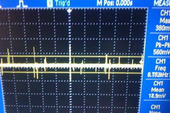
    I connected an inverter from a power socket. From very next power socket i connected a DSO.

    A 2KW motor is connected to the inverter.

    I probed an open end shielded cable. When i switch on the motor i get the following. I changed the power socket to another location then that noise is nil.

    Kindly advice on this.

    Regards

    Goutham 

  • Hi Goutham,

    It would still be helpful to scope capture the data signals from the encoder, before and after the optical isolator.

    In your original post you mentioned that your encoder works off 24V, but your picture from Dec-18 shows a 5V supply.  Which is it?

    In general, the best thing to do is measure the 4 wires for the encoder, at the encoder.  It appears that the power rails are unstable, which causes an incorrect signal output (extra pulses).  You may be able to solve this by electrically isolating the encoder's GND (and shield) from the motor, or by adding a capacitor at the encoder between PWR and GND to help filter the noise.

    Best regards,
    RE