This thread has been locked.

If you have a related question, please click the "Ask a related question" button in the top right corner. The newly created question will be automatically linked to this question.

DRV8829 EVM GUI control parameter

Other Parts Discussed in Thread: DRV8828

 Hi,

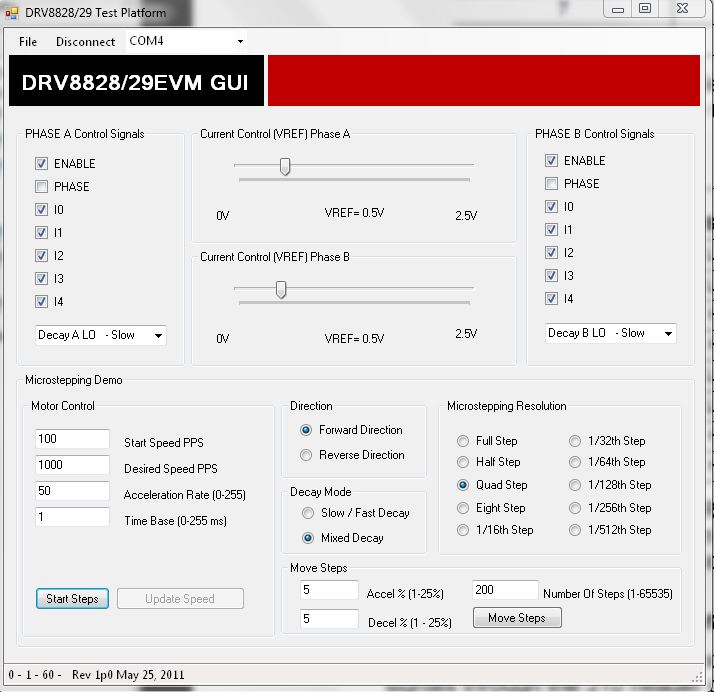
We are using TI DRV8828/29 evm for stepper motor control (datasheet attached, part number SST43D2100). I am trying to run this motor using TI GUI (CPG006_DRV88XX), but motor is not running smoothly and it is  loading power supply. Please provide necessity help and clarify below points


  1. Phase button should be checked or unchecked in GUI.
  2. Enable button should be checked or unchecked in GUI.
  3. Are GUI parameters are motor dependent if yes then please tell how to select them?


We are using 24VDC, 1A (set current limit) power supply and connecting motor terminal A,A_bar and B,B_bar to evm.

regards

Vinod8741.SST43D2100.pdf


  • Hi Vinod,

    One issue could be the value of VREF when running the motor. If VREF is greater than .5V, the current per winding is set to more than 1A. Since there are two windings, the current can be exceed the 1A limit set on the supply. Please increase the current limit of the power supply to 2A. Also please set VREF to .5V which is the target current per winding.

    Regarding your questions, I will have to confirm the settings for question 1 and 2. I will get back to you on this.

    The GUI settings are motor dependent. The VREF should be set on both to .5V to limit the current.

    Can you also provide screenshots of the settings you are using?

    Thanks.

  • Hi Vinod,

    I have a little more information on running with the GUI.


      Please set SW1 position 8 to low prior to powering up the board.
      Power up the board and the STATUS LED should begin blinking.
      Connect the GUI, and select CONNECT on the top of the GUI.

    Set the GUI to values shown and  then select "Start Steps"

    This worked after I changed the step to half step. To change direction, select "Stepping" (when running this is the same location as "Start Steps". Once stopped, select "Reverse Direction" and then "Start Steps".

    I hope this works for you. Please let me know if you run into any further issues.


  • Hi Rick,

    With these setting situation is better and motor ramp up to a constant speed and running smoothly. But still i am facing below issue.

    1. While motor ramp up it takes 2-3 sec and in this duration motor take maximum current i.e 2A (voltage also drop) , after that motor run smoothly with a constant current of 0.88A.

    2.While stopping ( pressing "stepping button") motor again take maximum current i.e 2A (voltage also drop) and then motor stop.

    sometime this ramp up increase too much and motor get heated. Please clarify why this is happening?

    Also i would like to tell you about my SW1 switch setting. I have put SW1.7 and SW1.8 at Low and rest are on HI position. Please tell if this is correct.

    regards

    vinod

  • Vinod,

    SW1.7 should be high to enable MCU operational mode and SW1.8 should be low to enable serial communication mode to control the EVm via GUI. Rest all can be set hi. Make sure that these setting are done before power-on for proper operation.

    I would suggest to set mixed decay mode thorugh GUI for proper operation.

    High current issue during ramp-up and down could be related to fast accelration rate, you can try to slow it down to reduce the current during these transeint condition.

    Best Regards

    Milan-Motor Application Team

  • Hi Milan,

    I tried with lower acceleration rate but it did not work, than i increase acceleration rate(200) it help me to reach desired speed in better time. But still some time it is unable to ramp up and draw full current then i have to restart the board

    And for ramp down situation is worst, most of the time motor locked up.

    Our ramp up requirements are approx 600 rpm within 150 msec.

    Please suggest what could be the issue. Also please suggest should i need to rotate POT R19 for some voltage ref.

    regards

    vinod

  • Hi Vinod,

    Sorry for the delay in getting back to you.

    I have found that the Pot R19 has no effect on the current regulation when using the GUI. Your best approach is to change R3 and R7 to .5Ohms. This will limit the current to 1A in both windings vs the .1Ohm/5A setting on the board. The user guide will be updated to make this limitation clearer.

    Also, I have confirmed that only the following 2 steps are required to spin the motor using the GUI.

    1) Connect
    2) Optional -- set the microstepping resolution if you wish
    3) Start Steps

    The motor I have did show similar startup and stopping problems as you described. I have not changed the resistors, and believe that is having an impact.

    After changing the resistors, you can tune the desired speed, acceleration rate, and time base to achieve the 600 rpm within 150ms.