I'm using stepper motor driver DRV8811..
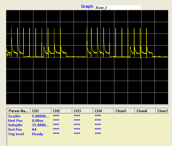
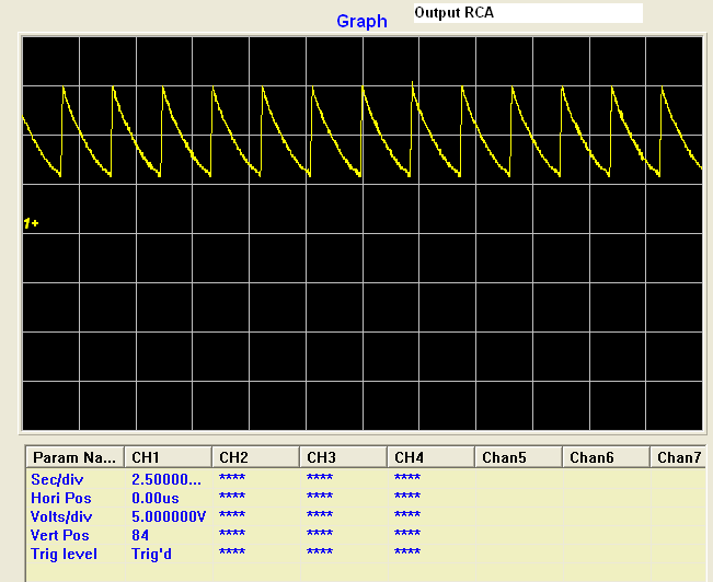
I getting output from Aout_1 and Aout_2.
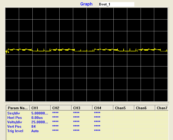
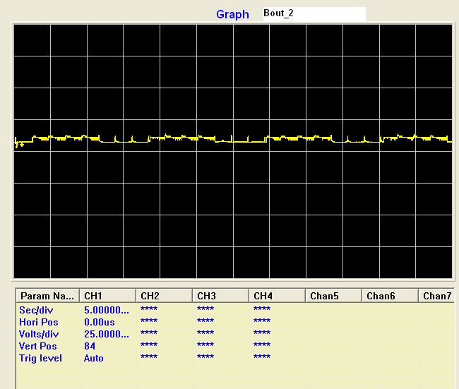
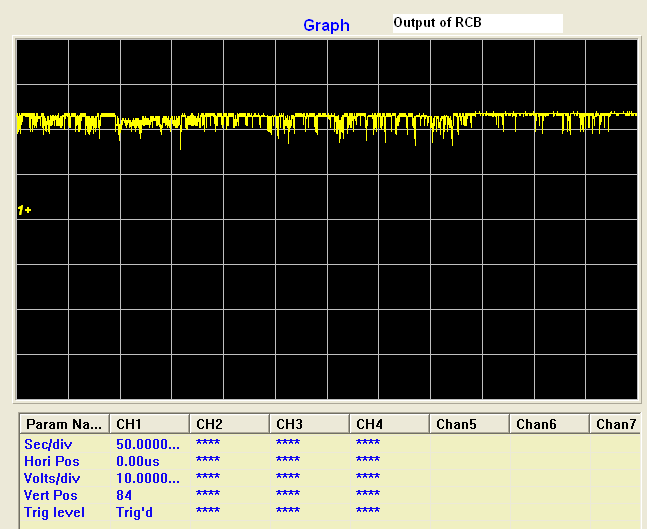
There was no output from Bout_1 and Bout_2.
It's same in all step mode.
I little bit confused... What is the problem???
This thread has been locked.
If you have a related question, please click the "Ask a related question" button in the top right corner. The newly created question will be automatically linked to this question.
Hi Mayilsamy
Have you checked all the hardware connection? I suggest starting from below points.
1. Check connection of current sense resistor from ISENB to GND.
2. Check configuration of RCB pin.
3. Motor windings of PHASE B, check whether opened.
4. Swap to a new device.
If still cann't find the problem, please post your schematic and PCB here for us to debug.
Thanks.
Wilson Zuo
Motor Application Team
Thanks for your reply..
When I power the device . Its working good..
after few seconds there no output in Bout_1,Bout_2..
So, is the device broken now or every time you power on, the issue will be the same?
Have you checked the output waveform, you can post it here if you have.
I still suspect the Rsense resistor. What is your current setting and power of the sense resistor?
And if your BOUTx failed, the motor should stop and vibrate, are you sure AOUTx is normal?
Thanks.
I also suggest checking your VREF voltage, and the associated ICHOP. And like Wilson said, RCA/RCB components, and DECAY voltage.
Best regards,
RE
Hi Mayilsamy
Have you checked the real value and connection of those components? Example, measure the resistance of both sense resistor on the issued board. check your motor's windings and the two phase resistors real value. Also could give the scope capture of your BOUTx when you said AOUT is normal.
A quick method is to swap the DRV8811 to a new one.
if the problem is just the same, then, we can say that there should be some hardware problems related to the PCB. Because there is almost no chance to met two broken parts with this kind of failure.
If the problem is gone, there should be some abnormal condition happened to the failure part and cause some damage to the parts.
Thanks,
Wilson Zuo
Hi Mayilsamy
I have added you as my friend and give my email address.
from your waveform, there should be something wrong with BOUTx. I have never seen this before. So really need you to give more descriptions about your debuging process.
Thanks.
Wilson
Hi Mayilsamy,
Can you confirm the capacitor for RCA/RCB is 0.1uF? The datasheet does not specify a minimum or maximum, but it was intended to be much less than this.
The recommended Rx should be between 12kOhms and 100kOhms, and the recommended Cx should be between 470pF and 1500pF. The datasheet of a similar device, the DRV8818, shows these recommendations.
Please be sure to lower the Cx capacitor to be within this range, and let us know if BOUT begins working properly.
Thanks.
Hi.. All.
My motor running video uploaded in my profile...
So, Kindly watch it....
Hi Maylisamy
The motor looks running normally at first several seconds.
I think may be the cause is related PCB ground noise, and if the ground is not proper, noise on DIR and STEP inputs pin may affect the normal running sequense. Could you try to put a external pull down resistor such as 3k to ground of DIR pin and STEP pin and test again.
Could you show us the board or the PCB?
Thanks
Wilson Zuo
Hi Maylisamy
Just realized that you have RCA/RCB == 33k ,0.1uf.
That means Blanking time = 140us and OFF time = 3.3ms. It is too long for most steppers. That will cause running problems.
It is recommended to change the C value within 680p to 1500p so that the Blanking time is around 1~3us commonly used.
Thanks
Wilson Zuo
Thanks.. For your reply at the earliest..
I changed the C value 1000p .. Motor starts to run..
Thank you..
And also motor making hiss sound (ringing).
How to rectify it.
Mayilsamy.A
Hi Mayilsamy
Glad to know it worked. The hiss sound is the currrent chopping noise. You can change the RC parameters to tune the mixed decay behavior. Please refer to datasheet Page9, 10 ,11 to optimize the fast decay and slow decay portion of the off time.
Usually the more fast decay time, the more current ripple and noise. But if fast decay time is too small, the current can't be regulated well as we want.
Also you can increase the PWM frequency by reduce the R*C value to lower the audio noise.
Thanks
Wilson
Hi.. Wilson.
I have one more doubt . Whenever I increase the Vref Voltage motor speed was automatically increased.
What is the step calculation?
How I control the speed of the motor??
Thanks
Mayilsamy
Hi Mayilsamy,
VREF will control the torque and should not have an effect on speed unless the motor does not have enough torque to overcome the inertia of the load.
Since this is a STEP/DIR part, one pulse on the STEP pin will correspond to one step/microstep in the indexer. Speed is determined by the frequency of the step pulses.