This thread has been locked.

If you have a related question, please click the "Ask a related question" button in the top right corner. The newly created question will be automatically linked to this question.

drv 102

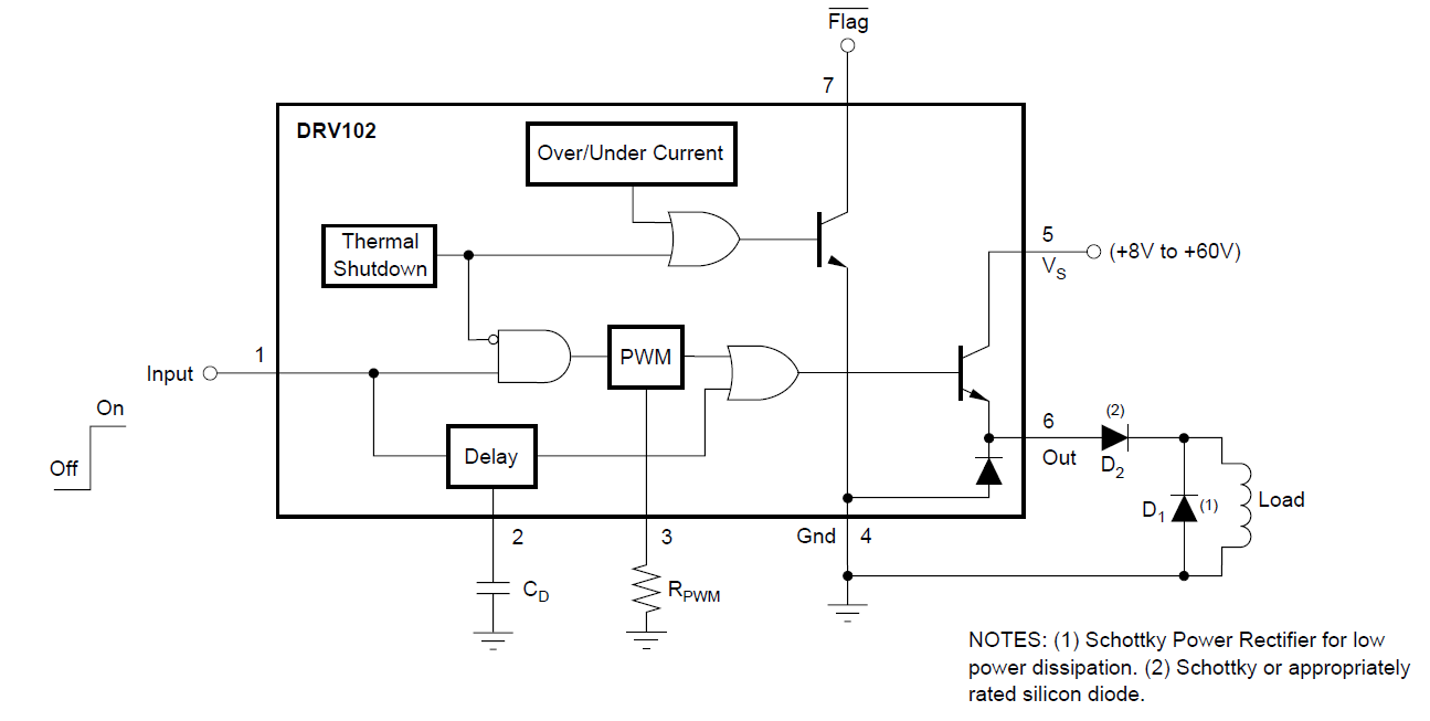
I am using DRV 102 IC for power conservation purpose in coil. specification for coil 24 Vdc, current 1.88A,

When I connect output terminal of IC to coil then IC  is heated but when i removed coil from this terminal then IC is not heated.Please any help me on this issue.

Is this happening because of common ground path for supply and coil?

  • Hi Mahesh,

    Can you provide additional information?

    Do you have a schematic that you can post?
    What is the state of the other pins?
    What is the voltage on the output pin without the coil connected?

    Thanks.

  • Thanks for Reply

    My design working is like this ,It's electromagnetic coil with 600 turns and inductance 0.9H,I give 24V dc to DRV at pin no.5 after one second pwm mode will start and voltage is reduced down to 16V in pwm mode.

    For 1 second 24 V given to coil at that time current is 1.8A and after that pwm mode starts and voltage reduced down to 16 V and current of coil is 0.47A.Now problem starts here,after two or three minutes current starts increasing from 0.48,0.49,0.5 ....and IC starts heating a lot.I put a Heat sink also put problem is not solved.

    Output voltage without coil connected is 16V in pwm mode which is mentioned above but IC is not heating at this time.

    I have not use heat sink which is given in Datasheet.

    I connect input supply negative terminal to pin no.4 which common ground for input and output.Is this  problem due to common ground/heatsink problem?

    Here I attached schematic of DRV 102.1)  At pin no.2 C=1uf for one second delay. 2)pin 3 16 Kohm  for pwm mode.3)pin5 DC supply 4)pin 6 out put 5)pin 4 ground

  • Hi Mahesh,

    If you attached the schematic, it did not appear. Would you please confirm one more schematic detail?

    Are diodes D2 and D1 in the Logic Block Diagram (page 4 of datasheet) installed as shown. Please note the description of pin 6, which states that these diodes are needed for inductive loads.

    Also, can you monitor the nFLAG output during the time the device is heating to determine if the device is reporting over-temp, over-current, or under-current?

    Thanks.


  • Thanks again for reply.

    My schematic is same as given in datasheet(page 4).

    Pin no.1 and pin no. 7 are left open

    here as you mentioned, i used other diodes (i.e BY255)but high voltage and current rating.I will try using schottky rectifier and diodes as mentioned in datasheet.

    What is your opinion about common grounding issue because supply ground and load ground are same,heat sink,and initial transient current?

    Thanks and best regards

    mahesh

  • Hi Mahesh,

    Did the results change when using schottky diodes? The lower forward voltage of the schottky diode (D1) will cause the current to flow through the schottky during the off cycle. If the forward voltage of the BY255 is higher than the internal diode, the current will flow through the device.

    I am also contacting the expert on the device. I hope to hear from him soon.

  • Hello Mahesh,

    As Rick said, using a schottky diode for D1 (see schematic below) will help prevent he internal diode in the DRV102 from conducting.


    In your application, B350, SS35 and MBRS360BT3G are good candidates for both D1 and D2.

    I do not see any issue with your connection of the supply’s negative terminal to pin no.4.

    I strongly suggest you use a heat sink in your application. Pages 13 and 14 of the DRV102 datasheet explain methods to calculate the heat sinking requirements of the integrated circuit. Assuming you can achieve an overall theta JA of 16.5 deg. C/W, you can expect a temperature increase of about 66 deg. celsius based on your power supply voltage and current measurements.

    Reiterating some of the things Rick said:

    -          Can you monitor the nFLAG output during the time the device is heating to determine if the device is reporting over-temp, over-current, or under-current?

    -          A schematic of your circuit would be helpful to ensure we are not overlooking anything.

    Hope this helps.

    Best regards,

    Jose