This thread has been locked.

If you have a related question, please click the "Ask a related question" button in the top right corner. The newly created question will be automatically linked to this question.

About DRV 8312 PWM switching

Other Parts Discussed in Thread: DRV8312

Hi,

I was using TMDSHVMTRPFCKIT for BLDC_sensorless project. The original settings of f2803xbldcpwm.h file is High side PWM switching and Low side ON (H_PWM_L_ON mode). However, my research involves PWM switching at the Low side of the transistors and I was doing fine with the codes in TMDSHVMTRPFCKIT.

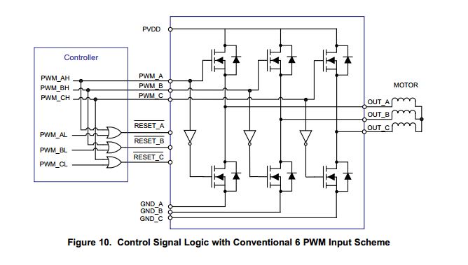
The problem is I've changed to DRV-8312 69m kit now and I have some difficulties understanding the codes and schematic of the switching inside the DRV-8312.

First, I copy some of the codes from the f2806xbldcpwm.h file from the project of DRV-8312 69m kit, shown below. Where is the EPWM 1B connecting to the Figure attached? Is it PWM_AL or RESET_A? 

EPwm1Regs.AQCSFRC.bit.CSFB = 0; 
EPwm1Regs.AQCTLB.bit.CAU = 2; 
EPwm1Regs.AQCTLB.bit.ZRO = 1; 
EPwm1Regs.CMPA.half.CMPA = (int16)(Tmp>>15); 
EPwm1Regs.AQCSFRC.bit.CSFA = 2; 

EPwm2Regs.AQCSFRC.bit.CSFA = 1;
EPwm2Regs.AQCSFRC.bit.CSFB = 2;

EPwm3Regs.AQCSFRC.bit.CSFA = 1; 
EPwm3Regs.AQCSFRC.bit.CSFB = 1;

Second, where is the RESET_A connecting to the MOSFET in the Inverter? From my understanding, the 6 MOSFETs in the inverter of the attached figure are controlled only by three singnals, the PWM_AH, PWM_BH and PWM_CH. In this case, how can the BLDC motor conduct only two phases per state?

My questions are a little bit complicated. To sum up, I just want to know what is the difference of the PWM switching between these two kits. My goal is to apply PWM switches on both High side and Low side of the transistors. Any help would be greatly appreciated. 

Best regards, Samuel


  • I've search some related post in this forum, I still cannot understand it. 

    Take this one as an example, 
    http://e2e.ti.com/support/applications/motor_drivers/f/38/p/272897/954069.aspx#954069

    Chris mentioned that 

    '' PWM_A, B, and C are the high-side transistors, and the low-side are automatically getting the low-side IF THE phase is active.

    C is not-active (note that RESET is low), so all current must flow between A and B.'' 

    So what is the code i can use to connect the RESET? is it the EPWM B? 

  • Hi Samuel,

    I am getting in contact with the right person to answer your questions.

    Best Regards,

    John

  • Samuel,

    For BLDC Trap we are using 4Q BiPolar PWM technique.

    Think of the RESET line as making the Half bridge active or not.  So if you are using legs A and B you will have a RESET (with line over it) of 1 on both, and leg C will be 0 (non-active).  So these reset signals just work their way through the 3 possible combinations during BLDC trapezoidal control.

    A & B active

    A & C active

    C & B active

    You use the PWM_A output from the MCU to control the duty cycle command to the high side leg.  The low side complementary command is made for you.

    you can see this in Figure 11 of the DRV8312 datasheet.


    If you are using the DRV8312 for continous sinusoidal waveforms you just leave the RESETS active all the time.


    * Personally, I would have called these pins ENABLE instead of RESET.


  • Hi Chris

    Thank you so much for you answer!!

    Best regards, Samuel