This thread has been locked.

If you have a related question, please click the "Ask a related question" button in the top right corner. The newly created question will be automatically linked to this question.

DRV8711 Pull-up to SCS pin?

Other Parts Discussed in Thread: DRV8711, DRV8711EVM

Hello Friends,

I am a newbie.

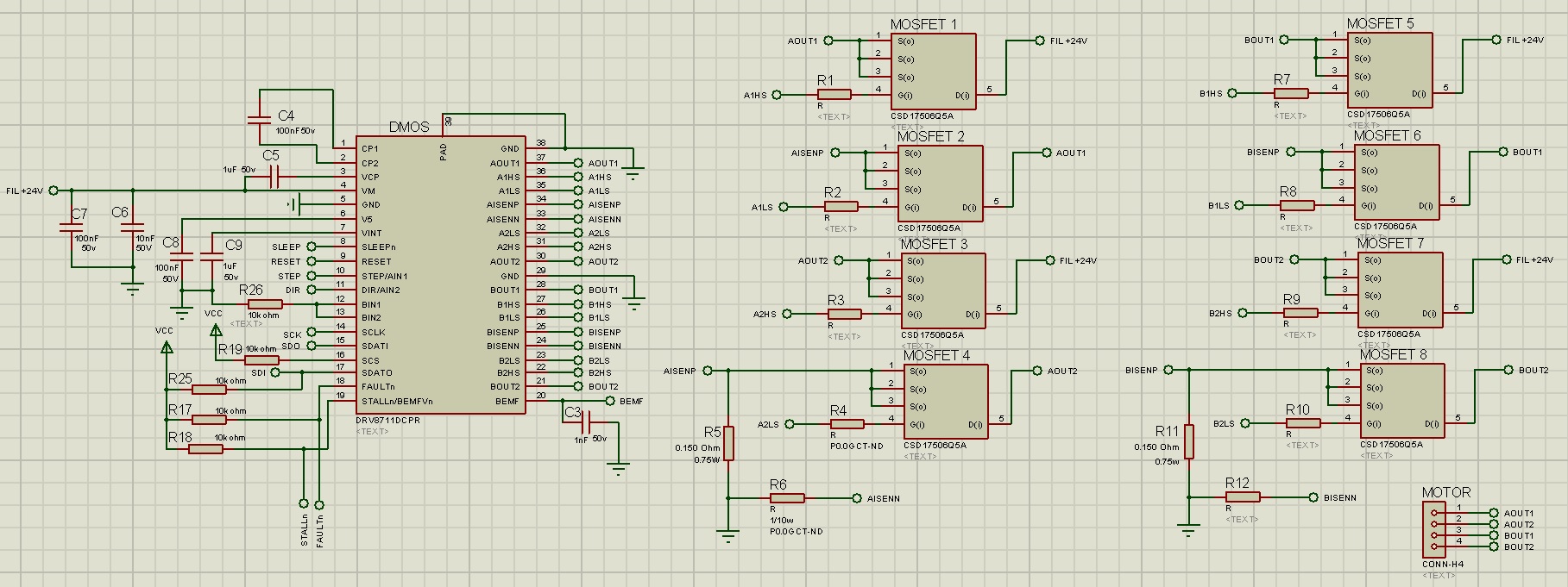
I designed a motor driver card, include a mcu and drv8711.
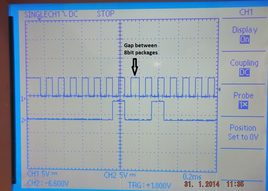
I am trying to programme drv8711 with SPI.

I only put a pull-up resistor to SCS pin of DRV8711 and not connect SCS pin to MCU.
I thought, it is enough to pull SCS pin high in order to execute SPI communication.

Now ı cant programme the driver.


I want to know, is this a problem (never apply low logic to SCS pin)?

Thank You!

  • I don't believe this should be an issue. Do you have a pull up on SDATO as well?

    Can you check that the MCU is sending the correct waveforms (scope shot)?

  • Hi Erhan,

    We will have to confirm that this configuration will work.

    There are three questions to ask before further investigation.

    1) What value pullup resistor did you use? There is an internal pulldown of approximately 100kOhms. If the resistor is too small, the input is not seen as a logic high. Please make sure that the voltage on SCS is greater than 2V.

    2) Does the system have more than one SPI slave? If so, the transactions to the other slaves using SCLK could be causing the DRV8711 to get out of sync. It is also possible that noise on the SCLK line could cause the DRV8711 to get out of sync. Many mcu float the input upon reset. If an edge is detected on SCLK, the SPI can be out of sync from then forward.

    3) Do you have the ability to read an SPI transaction using a scope? If so, can you capture a read of the CTRL register? This will allow confirmation that the DRV8711 is synchronized to the SPI and is responding to the read command properly.

    Once you report back that these are not causing the problem, we will continue our investigation.

    Thanks.

  • Thank you for quick reply.

    1) There is a 10k pull up on SDATO. You can find the schematics of the PCB below. I think MCU is sending the correct waveform. I am sending the scope shot as attachment. These are the scope shots of the same signal with different zoom levels.

    2) The voltage on SCS is 4.5V.

    3) System have only one SPI slave (drv8711). Is resetting drv8711 clear any out-of-sync transaction? I am resetting the drv8711 before transaction and then send the data.

    4) I also checked the physical connections between MCU and drv8711.

    Thanks.

  • Hi Erhan,

    Thank you for the details. From the screenshots, it appears that the DRV8711 is communicating with the mcu.

    According to the datasheet, issuing a reset will clear the SPI interface and re-synchronize it.

    We will attempt to read on our side using the same procedure that you have performed. Can you confirm that this is the first read of the DRV8711? Is nSLEEP a logic high or low? If RESET was issued, was it issued while nSLEEP was a logic low?

    Looking through the schematic, I noticed a couple of items that should be addressed:
    1) Do you have bulk capacitance on VM? Please examine the DRV8711EVM for examples, but there is usually a 100uF bulk on the board, plus a 10uF and .1uF ceramic near VM. At the DRV8711EVM folder, scroll down to the Software line. The zipped file contains the schematic, layout, and firmware used for the EVM.
    2) Please note that the xISENSx circuitry has been modified. Page 16 of the datasheet now recommends that either no resistors or two symmetrical resistors are used in the. In your case, it is recommended that the resistor is zero.

    I will have a further update soon.


  • Hi Rick,

    The initial state of the clock pin is low. The pin is set to high when I set the SPI parameters inside the code. Therefore, initial state change may result in a synchronization problem. But I reset the DRV8711 before SPI communication and according to datasheet this should re-synchronize the communication. 

    I tried to write CTRL register with and without a RESET while nSLEEP is low and nSLEEP is high but nothing has changed. I tried to read CTRL register by sending (1000 0000 0000 0000) but the SDATO pin is high and there is no signal during the spi clock, DRV8711 is not responding to read operation. SCS pin is 4.5V. I checked the VM pin of the DRV8711, it is +24V. All the pin connections between MCU and DRV8711 is double checked. Stall and fault pins are high. I also changed the PCB and perform the same tests in case of any damage to the previous board.

    1) I sent only a part of the schematic. There is also a power-line that contains varistor, TVS, two 100nf 100V ceramic cap (used to support varistor and TVS), one 220uf 50V bulk electrolytic capacitor and a 10uf 50V ceramic capacitor. The power-line is connected to the VM through 100nf 50v and 10nf 50v ceramic capacitors near VM pin.

    2) In the schematic, all the resistors connected to the xISENSx pins (which are denoted as R ) is zero ohm resistors.

    Thank you for your help.

    Best Regards,

    Erhan

  • Hi Rick,

    I solved the problem by connecting the chip select pin to the MCU via an external cable and now everything is working fine. The problem seems to be out-of-sync of communication. I think the initial state change of the clock-pin is the reason of the problem and the RESET pin doesn't initialize the communication as it is written in the datasheet but I am not certain about that, it should be double checked. As a result, pulling up the chip select pin is a very bad idea and it cost me more than 3 days :)).

    Thank you for your help.

    Best Regards,

    Erhan

  • Hi Erhan,

    I am glad to hear that you have everything working. Looking through the code we use, SCS is used to frame the transaction. From your description, it does appear as though the communication is out of sync. I will investigate further tomorrow and confirm.

    Thank you for all the debug work on your side.

  • Hi Erhan,

    As you have observed, SCS is required for proper SPI operation. For writes, it is listed in the datasheet in the SPI Interface Timing Requirements (page 8). Please look at the parameter tL(SCS) which is "Inactive time, SCS (between writes)".

    SCS must be driven to a logic low to complete the write (or begin a new read) transaction.