This thread has been locked.

If you have a related question, please click the "Ask a related question" button in the top right corner. The newly created question will be automatically linked to this question.

Built a Line follower, need advice for improvements

Other Parts Discussed in Thread: DRV8839EVM

Hi,

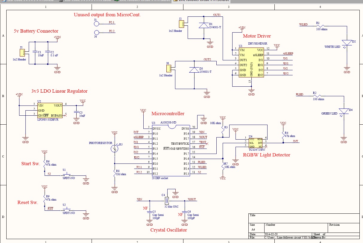
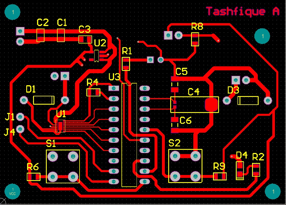
I made a Schematic and a 2-Layer PCB. Did it in Altium. I was hoping to receive some professional advice to become a better hardware engineer. 

If you are wondering about the 3d view, I made the body with the motors and the wheels in SolidWorks and then transferred it into Altium.

Thank you.    

  • Hi Tashfique

    Nice 3D view making and an interesing front wheel.

    Since your board is not so tight for placement, you can make a solid GND plane for all. Other wise, you should make sure the high current trace not affecting the signal trace and its grounding (That may cause negative voltage to input pins). Pay attention to all the current backing path in GND plane or trace too.

    Or the caps for VM or VCC should be placed closing to VM or VCC pins of the driver device other than connector (I think your placement of caps is not so proper).

    Besides, you should pay attention to the seperating of high speed and low speed signal, digital or PWM to analog inputs.

    Thanks.

  • Hi Tashfique,

    In addition to Wilson's comments, you can also examine the gerbers of the DRV8839EVM. These can be found by searching for the DRV8839EVM and moving down to the software section. The most current zipped file contains the schematics, gerbers and firmware for the EVM.

    The direct link is http://www.ti.com/lit/zip/slvc524