This thread has been locked.

If you have a related question, please click the "Ask a related question" button in the top right corner. The newly created question will be automatically linked to this question.

DRV8332 With high inductance PMSM

Other Parts Discussed in Thread: DRV8332, DRV8312

Hello!

I have an application, where I have to drive a PMSM motor, with a notably high inductance value of 820uH.

I made a PCB board for development with the DRV8332 using the available reference designs and app notes.

I use the OC latching shutdown mode with a 19kOhm OC adj resistor.

The drive PWM has a frequency of 36kHZ, the modulation method I use is Space Vector Modulation PWM.

The DRV8332 seems to shutdown at a little over ~4A continuous current, driving PVDD at ~22V. 

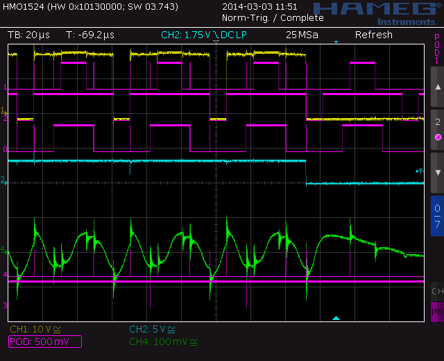
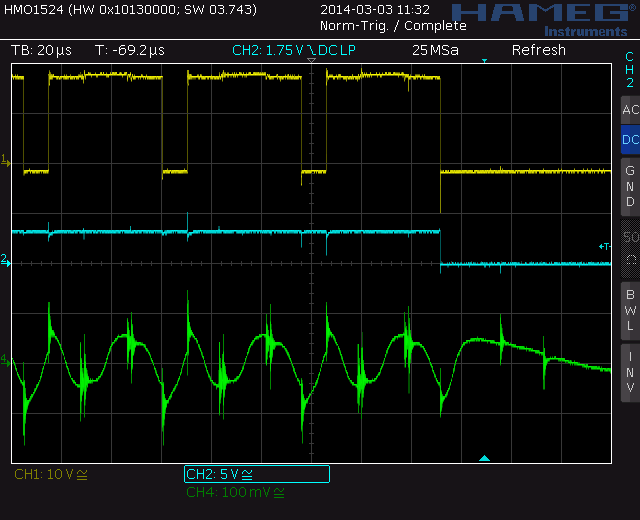
After performing various measurements with a current clamp on an oscilloscope, it seems like that there are huge current spikes, measured at the motor input. By huge spikes I mean around and above 12A spikes.

The DRV8332 sends a fault signal, which in my opinion are because of the high current spikes on the bridge outputs.

Now it seems interesting that even though the motor has a highly high inductance, which should by my knowledge slow down inrush current, therefore eliminating current spikes, the spikes still occure.

My question is, is there anything that should be followed, when using the DRV8332 with high inductive loads (e.g. high inductance PMSM, where the inductance is ~820uH)

Every insight on this would be highly appreciated.

  • Mate,

    Do you have any scope captures showing the phenomenon?  Is the FAULT a latched condition - i.e. you have to cycle the /RESET pins to recover the drive? 

    Also, what is the time length of the current pulses?  If they are in nanoseconds, it could be an artifact of the current probe (I have been fooled by this before).  This shouldn't be enough time to trigger OC protection as our holdoff time is ~250ns. 


  • Ryan,

    i work together with Mate on this project, i will capture some scopes tomorrow.

    The initial problem was that the device went OC/UV-protection mode with a current way below the limit set by the resistor. (around 4A instead of 13.2 A) Operational mode is OC latching shutdown.

    Do you have an idea what could cause that?

    Thanks,

    Wolfgang

  • Ryan,

    Here i have some captures.
    CH1 (Yellow) is the voltage on the motor in the A-line
    CH2 (Cyan) is the voltage on the FAULT-pin
    CH4 (Green) is the current to the motor in the A-line (100 mV = 1 A)
    POD.0-2 are the µC-PWM-ignals to the driver 

    I also captured the other lines seperately (without POD), you can see not all half-bridges stop operation, so i can only assume that the overcurrent protection has triggered.

  • I wouldn't call 800uH high inductance...but it's on the higher side  800uH is just a bit higher than the very standard BLDC that ships with our DRV8312 kits.  It's MUCH higher than the 2.5uH inductances of these hobby motors people are using.

    Higher inductance is good for you generally as it reduces the short circuit current / current ripple.

    What I see in your pictures looks like poor current control. This could be caused by

    - poor current samples (board layout?, at high modulation areas?, low current on a high current scaling?)

    - poor rotor angle measurement/estimation

    - too slow of controller updating at higher speeds and no high speed compensation

    - poor controller tuning


    Why are you PWMing so high for this motor?
    What SW are you using?


  • Wolfgang,

    Can you share your schematic and layout?  This would help validate some of Chris' concerns around the hardware section used for current sensing.


  • Thank you both!

    We switched to a DRV8301-Kit so our development on the DRV8332 is paused.