This thread has been locked.

If you have a related question, please click the "Ask a related question" button in the top right corner. The newly created question will be automatically linked to this question.

DRV 8432 parallel mode malfunction

I am using the drv 8432 in the parallel mode. I am NOT driving a motor but an inductive coil (L=470 uH and R = 0.4 ohm). I am using this IC to apply a specific voltage pattern to the coil and recycle the reactive power of the coil back to my supply. 

i.e. When PWM_A is high and PWM_B is low - current pumped from source to the coil from OUT_A and OUT_B and returning via OUT_C and OUT_D

When PWM_A is low and PWM_B is high - current pumped to source to the coil from OUT_C and OUT_D and returning via OUT_A and OUT_B

Always maintaining them complementary. 

I have set the R_adj = 24 ohm (CBC at 10.7A) - My application requires peaks of 18-19A. (Assuming IC will not protest till  20A.)

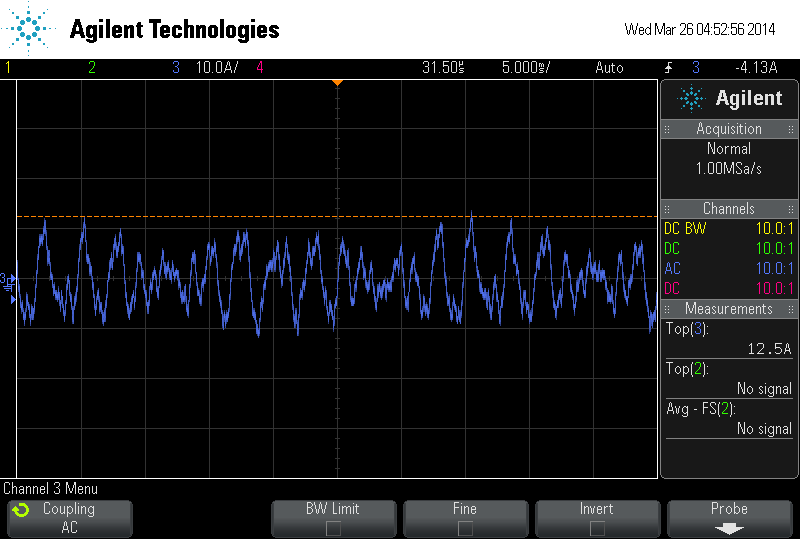
When I connect only a combination of 2 outputs, i.e A,C or A,D or B,C or B,D, the IC works beautifully and limits the current at 10.5A (expected since there must be error in resistor value). I have observed the current using a current probe.

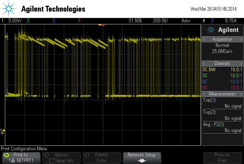
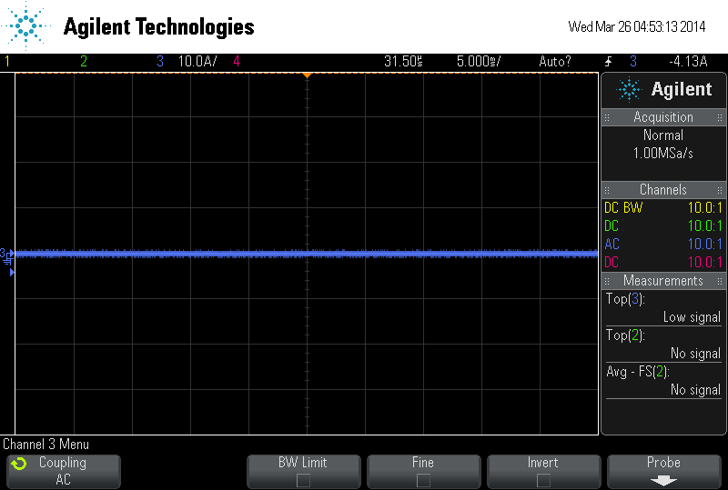
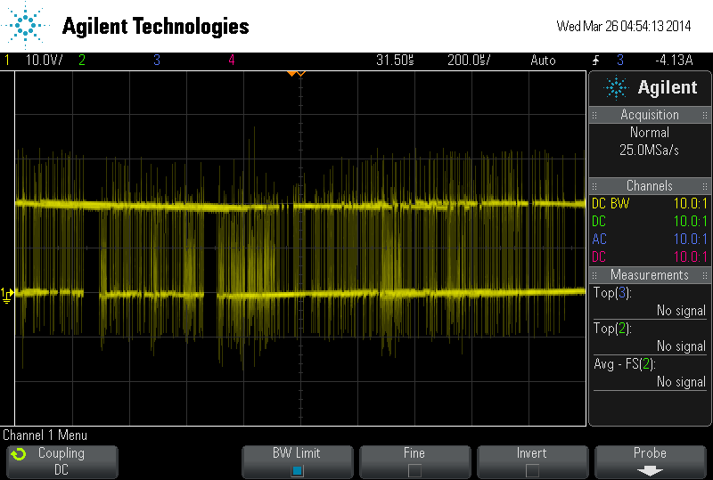
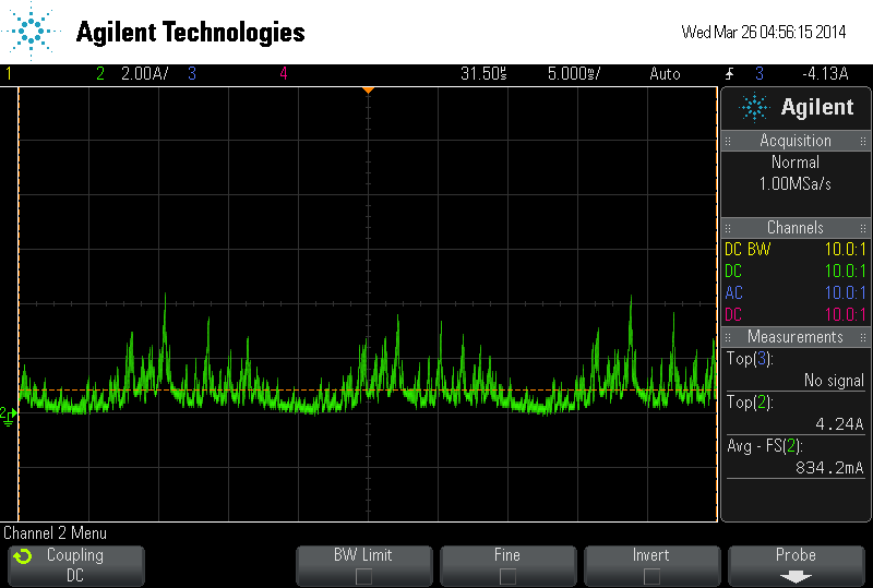
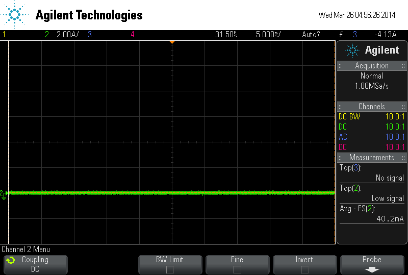
However when I join A,B and C,D and try to squeeze out anything above 12.5A. the IC goes in OC shutdown NOT CBC. (fault = 0 otw =1) The current probes measured between 6-6.5A in all the outputs before the IC shutdown. There were no stray transients to cause the shutdown.

OC shutdown should not happen in parallel mode. Note: Current is being ramped up gradually so no possibility of the IC interpreting a short current arises. 

I have attached a reasonable heat shield and observed that temperatures are below 60 degrees even at 12 A.

I have used inductors in series with all the outputs before directly connecting them. The values are twice that of minimum required as calculated from the data sheet.

How is it possible that an output can sustain 10.5A without any hiccups and cause a OC shutdown at 6A when connected in parallel? 

I have a ground plane as recommended and separated the GND and AGND with a1 ohm resistor.

Please advise.

Sincerely,

Rohit Joshi

ECE, Georgia Tech

  • Hi Rohit,

    There is another possibility to rule out before looking into the OC shutdown. Please note the fault = 0, otw = 1 can also mean a GVDD undervoltage.

    Please check the GVDD_x and BST_x pins looking for droops below approximately 9.5V. This can be caused by the duty cycle being too high or some other event.

    Once this is ruled out, the troubleshooting can continue. Please provide any additional information such as schematics, layouts, and screenshots that will provide a clearer picture of the problem.

    Thanks.

  • Hi Rick,

    I had already checked that possibility. All the GVDD_x and BST_x pins are above 10.5V throughout the entire operation. I have set my GVDD to be 12V.

    Attached are the graphs describing my problem.

    1. Current when only two outputs are sourcing current to the coil. Graph shows the current through the outputs just before the the CBC is reached.

    2.  Current when only two outputs are sourcing current to the coil. Graph shows the current through the outputs after voltage is twice that in fig 1. CBC is active.

    3. Current when all 4 outputs are sourcing current. Graph shows the currents (individual through one output and total) just before my issue arises.

    When the total current is increased beyond 12.5A, the IC goes in OC shutdown. I am concluding that my unique use of the IC to drive a coil is not causing the problem since the device was perfectly meeting expectations when only 2 channels were sourcing.

    6428.graphs.zip

    Thanks
    Rohit

  • Hi Rohit,

    Are you using the DRV8432EVM?  Can you provide schematics and layout of your system?

    As you are using the device to recycle the reactive power of the coil back to my supply, seeing the schematic and layout may help determine what is occurring.

    Thanks.

  • Hey Rick,

    I wasn't using the EVM. I was using the board already available before I joined this project but could not find anything amiss in it. Attaching the schematics and layout. 

    Note: None of the filter components on the output (after paralleling) are soldered. The provision was made but is not currently required. Also capacitors cm1 and cm4 are not soldered. The bottom plane is a ground plane.

    I also tested my arrangement with an EVM. The desired outputs were obtained. 

    There is something incorrect in the layout. Please help me find out what is going wrong.

    Rohit

    0525.Schematic_sig-gen_2012_12_06.pdf

    6740.PCB_sig-gen_2012_12_06.pdf

  • Hi Rohit,

    Thanks for the schematic and layout.  What is connected to 1- and 1+ of the connector? Since this is not a motor, it may also help explain what is occurring.

    Any screenshots of the inputs, outputs and bst signals when the shutdown occurs will also be helpful.

    Thanks.

  • Hi Rick,

    My coil (L=470 uH and R = 0.4 ohm) is connected between 1- and 1+ of the connector. 

    Attaching screenshots:

    1. BST signal just before shutdown.

    2.BST signal after shutdown.

    3. Output current just before.

    4. Output current just after.

    5. Output voltage just before

    6. Output voltage just after (~= GVDD voltage)

    7. Current from supply to main input capacitor jon PVDD just before.

    8. Current from supply to main input capacitor on PVDD just after.


    Didn't provide GVDD voltage since it was rock steady at 12V, both, before and after the shutdown.

    Thanks,

    Rohit

  • Hi Rohit,

    It may be that the BST undervoltage protection is affecting your operation still. In screen capture 1, the BST signal is drooping approximately 3V. This is the danger area where the device can turn off the outputs.

    Please add a larger capacitor on your BST pins and look for improvements. See the page 11 of the datasheet for recommendations (220nF is recommended if you do not have a 5 Ohm resistor in series with the GVDD_x pins). If this does improve the performance, add a 5 Ohm  in series with the GVDD_x pins and increase the 220nF to 1uF.

  • HI Rick,

    Sorry for the late reply. I can't see the BST signal dropping below 10V. I believe you may have not seen the the ground reference point. It is about 2 units below the lowest point of the signal. That is about 10V.

    Rohit

  • Hi Rohit,

    You are correct that BST does not drop below 10V with respect to GND. However, BST does drop below 10V with respect to the OUT_x pin. This is also being monitored.

    If the OUT_x is set high for too long and BST-x minus OUT_x drops below approximately 10V, the outputs will be disabled. This circuit (BST_UVP) is to protect the high side FET. See page 11 (Bootstrap Capacitor Under Voltage Protection) for more details.

  • Hi TI Tech member,

    Is it make sense that the DRV8432 still continue operating normally when the fault pin is 'Low'? I'm driving the DRV8432 in OC latching mode with maximum setting at 11.6A. The fault pin become 'Low' a few seconds after the BLDC motor start to turn. However, the driver never shut down but motor seems to turn even smoother after the fault pin asserted low. I thought that the driver suppose to shut down permanently until we make the reset signal low and high again.

    Pls advice, thank you.

    Sincerely,

    Joe

  • Hi Joe,

    Can you share a schematic of your design?

    What else do you have connected to the FAULT pin?

    How does OTW respond?

    What operational mode are you in?

    You can send me the schematic offline by sending a friend request over E2E if you do not wish to share publicly.

  • Sorry about the hiatus.

    There doesn't seem to be any undervoltage on the BST pins with respect to the OUT pins. I have almost accounted for all the precautions mentioned on page 11.

    I soldered a new board with some layout modifications to see if it made any difference. My currents are reaching peaks of up to 17 A instead of the value of 12.5A. This is good but the same problem persists. Instead of CBC, the device enters OC latching. 

    Please note: OC adjust resister is 22k which is the lowest recommended value. According to that I should theoretically be allowed to reach 23.2A peak. Accounting for practical errors, I would be satisfied even if the device switched off at 20A. However, I am still puzzled while it shuts off at 17.7A. 

    Regards,

    Rohit