This thread has been locked.

If you have a related question, please click the "Ask a related question" button in the top right corner. The newly created question will be automatically linked to this question.

DRV8332 has high current in 50% duty cycle

Other Parts Discussed in Thread: DRV8332

Hi.

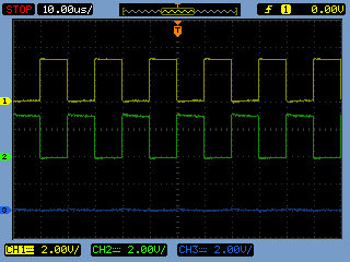
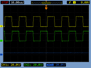
I am trying to develop 3 phase bldc motor drive board by trapezoidal commutation with hall sensor. I am using DRV8332 drivers to drive motor but the driver is high current, about 1.2A, in 50% duty ratio. I think the driver has low current in 50% duty ratio. I don't know why it is. It looks like normal except the high current problem.

Best regards.

Lee.

  • Hi Sungchoon Have you tried different U V W sequence? There is one possibility that the motor can run with big current in a false sequence. Thanks.
  • Hi Wilson

    Thank you for your rapid reply.

    I have checked the commutation sequence of the motor I used as you commented but it's correct. So I tested the driver chip, DRV8332, with a external pwm source in 50% duty ratio. I guess the output of the driver is in idle state as following paragraph from the datasheet of DRV8332 but it's 50% duty ratio pwm. I don't know this output is correct or not. Please let me know if you have any comment for this. Thanks

    "In six step trapezoidal complementary control scheme, a half bridge with larger than 50% duty cycle will have a positive current and a half bridge with less than 50% duty cycle will have a negative current. For normal operation, changing PWM duty cycle from 50% to 100% will adjust the current from 0 to maximum value with six steps control."

  • Lee,

    What is your applied PWM signal pattern? To get zero ouput voltage/current at 50% duty cycle, you must apply inverted or complimentary PWM to two active legs of H-bridge, while in the un-energied leg both switches should be off by resettting.

    It would be if you can show Input/ output PWM waveforms scope-shots from actual set-up to better understand the issue.

    Best Regards

    Milan

  • Milan

    Thanks for your reply.

    I attached the schematic and scope-shot.

    The following is input/output pwm scope shots. I input 50% duty ratio pwm signal to PWM_A pin of drv8332 and input a inverted signal to PWM_B pin of it. PWM_C pin is reset.

    CH1: PWM_A, CH2: PWM_B, CH3: PWM_C

    The following screen shot is driver's output for above input conditions.

    I don't know why the output is not zero.

    CH1: OUT_A, CH2: OUT_B, CH3: OUT_C

    Thanks

    Best regards.

  • Lee,

    Everything is working perfectly fine and DRV8332 outputs are as expected.

    You see in switching H-bridge, the notion of zero voltage is meant for average voltage over a PWM switching cycle. It not meant for instantaneous voltage. The average differential voltage applied across OUT_A and OUT_B is zero in your second scope capture.  For 50% of time, OUT_A high, OUT_B is low so differential voltage OUTAB is +12V and remaining 50% of time, OUT_A low and OUT_B is high so differential voltage OUTAB is -12V, effectively over as PWM cycle average voltage is zero.

    I hope above explanation clarifies your doubts. Let me know if you need further clarification.

    Best Regards

    Milan