This thread has been locked.

If you have a related question, please click the "Ask a related question" button in the top right corner. The newly created question will be automatically linked to this question.

2MTR-DYNO and DRV-8301-69M-kit

Other Parts Discussed in Thread: 2MTR-DYNO, DRV8301-69M-KIT, LVSERVOMTR, MOTORWARE, DRV8301

Hello, I just received the 2MTR-DYNO kit from TI, I have the DRV8301-69M-KIT.  Currently, I need to connect one of the motors to the 8301-69M-KIT.  The motor has the 16-pin Molex, was i suppose to receive the mating connector to the kit to connect one of the motors to the kit?  none was included in the package, I thought TI would include the mating cable to go from the 16-pin molex from the motor to the connectors on the 69M-kit.  What is the part number for the mating cables so I can buy two of them for both motors.

There was no documentation included in the 2MTR-DYNO box.  Can I run some of the labs in the instaSPIN projects and Lab User's Guide?

  • Hi Michael,

    We will check into this and get back to you soon.

  • Hi Michael,

    One part of your question can be answered by examining the motor product file at http://www.ti.com/tool/2mtr-dyno

    Pull up the motor pdf under the What's Included section. Page 3 has the connector information you want.

  • Michael,

    When I created 2MTR-DYNO the intent was to use this with a new 2MTR board which has the Molex connectors on-board...but we have delayed the release of this 2MTR board indefinitely (you will see 2MTR support through the LaunchPad + BoosterPack ecosystem later this year, but it will be bare wire screw down terminals)

    When I set-up the LVSERVOMTR (which is just a single one of these Teknic motors) I went ahead and included the wiring harness to break out the Molex to bare wire.

    Perhaps I should sell the wiring harness separately for 2MTR-DYNO users?  It will take a few months to do that, so in the meantime I suggest just creating your own.

    Yes, you can drive the motor in 2MTR-DYNO with your DRV8301 EVM and the MotorWare Projects. This Teknic motor is the default / test motor used for all DRV8301 EVM MotorWare projects (torque, velocity, and position control).

    If you actually want to run it as a Dyno I suggest using a 2nd DRV8301-69M-KIT, connet their Vbus to the same power supply, and on the dyno run InstaSPIN-FOC Torque control (proj_lab5a).  This will allow you to command a specific amount of current / torque as a load.


  • Chris,

    Question regard this dyno system:

    My understanding is: The system is pretty much a motor (M) driving a generator (G). So, the G is operating at Torq mode (by 69M kit) while the M is operating at Spd mode (by 2nd 69M kit). Then, the G is "providing" torq(+) while the M should provide reversed but same amount of torq(-), to have steady-state speed (acceleration = 0). So, actually, the M is consuming energy from the DC bus. And since G's torq and speed are in opposite direction, it is absorbing energy from M, and feeding DC bus.

    Am I right on above understanding?? If so, then the current of DC bus supply should be zero due to the balance of energy??

  • Yes.  The M may be used in velocity or position mode as well.  In fact the G can be used in those modes also, though Torque control is most typical for providing a load.

    Also, for the M you can use a different motor.  We are about to stock a low voltage induction motor that will also mate to this DYNO.

    And yes, with the DC bus connected to both you are getting very close to 0 current so you can work on motors with current demands even higher than your power supply.

  • Thanks a lot, Chris. You are always effective, helpful and friendly... 

    Hope some "stumbled up" person in this forum won't bother your weekend mood. You actually did very well to put yourself in our shoes all the time and please believe that most of us are very grateful.

  • Thank you for that, Mr. Yu. 

    Enjoy your weekend as well and have fun with your induction machine!

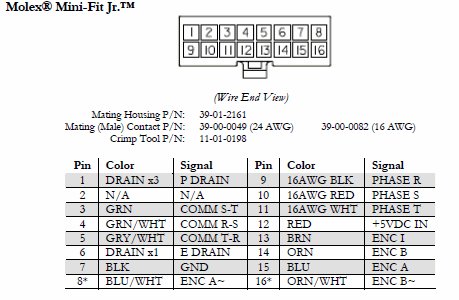
  • Hello Chris.  I'm creating the connectors (Harnesses) for the 2MTR-DYNO motors.  from the manual, this is the connector on the motor:

    Now as we see, PINS 9,10, and 11 are the 3-phase motor input.  For the encoder, I have ENC A, ENC B, ENC I, +5VDC IN, and GND, that's pins 15,14,13,12, and 7 (on the Molex)  going to J4 (pins 1,2,3,4 and 5) the 8301-kit.  I don't know much about how to connect the Hall Sensors  What pins on the molex are the hall sensors, and how do I connect to pins 1-5, J10 on the 6301-kit.  and, what are COMM R-S, S-T, and T-R, and how do I connect them on thekit.

    Thank you.

  • Here is the mapping.

    So for J10 the main Hall lines are 3,4,5, 12, 7 I believe...if order is same as the encoder, which I think it is. You can verify on the DRV83x schematic.

    DRV8301-J4
    Blue 24 AWG 26"
    Orange 24 AWG 26"
    Brown 24 AWG 26"
    Red 24 AWG 26"
    Black 24 AWG 26"
    DRV8301-J10
    Green 24 AWG 26"
    Green/White 24 AWG 26"
    Gray/White 24 AWG 26"
    Red 24 AWG 26"
    Black 24 AWG 26"
    DRV8301-Outputs
    White 16 AWG w/ferrules 18"
    Red 16 AWG w/ferrules 18"
    Black 16 AWG w/ferrules 18"
    Clear (or green) 16 AGW w/ferrules 18"
  • back in the office and looking at my cable.

    Molex Connections

    1-GND (green phase)
    2 - NC

    J10
    3 - Green
    4 - Green/White
    5 - Gray/White


    6 - NC
    7 - two black (negative power for J10/J4)
    8 - NC

    Motor U,V,W
    9- black phase
    10- red phase
    11 - white phase

    12 - two red (positive power for J10/J4)

    J5
    13 - brown
    14 - orange
    15 - blue


    16 - NC


  • Chris,

    DRV8301-69M-kit has 3 phases and 1 ground output.  Pins 9,10, and 11 on the molex (for the 2MTR-DYNO)  are the phases out.  Which pin on the molex is the ground output to the motor, or do I need to have ground on this type of motor?

    I don't think it's pin 7, since it's not green, and it's not 16AWG.

    Thanks

  • Michael,

    You don't have to connect the GND terminal on the DRV8301 EVM to anything.  We don't see enough noise issues to warrant it, but if you do it should be MOLEX PIN 1, the green GND wire.