This thread has been locked.

If you have a related question, please click the "Ask a related question" button in the top right corner. The newly created question will be automatically linked to this question.

DRV8711 - Poor microstep accuracy?

Other Parts Discussed in Thread: DRV8711

I'm actually doing some pre-qualification tests on the DRV8711 and two other drivers from competitors. One of the testpoints is to compare the microstep accuracy. I used an Oriental Motor PK268-E2.0B with coils in parallel (2.8A nominal current), DRV8711EVAL at 24V power supply and an Heidenhain Encoder with 1024 lines with 1Vss output, processed by a Beckhoff EL5201 with 1024-times interpolation (leading to a resolution around 2,912 increments / degree).

General settings: All default exept the following: GAIN=5, TORQUE=61 (leading to 4.0A peak?)


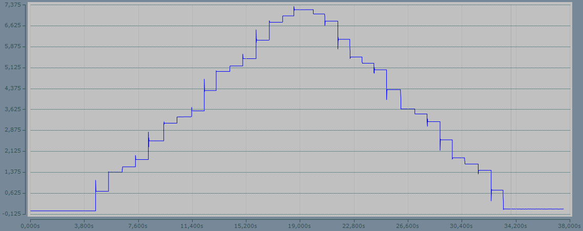
I run the motor in 1/4 step mode with 16 single steps forward and backward and recorded the actual position with TwinCAT scope. The values were transfered to an excel sheet were I calculated the position error as well as the relative inaccuracy (in % of a quarter step). I started with DECMODE=001, as I found this gives better high speed performance than the default setting. But with this setting, the accuracy was very poor. In some positions the relative error reached 120% and even more. Going back to DECMODE=100 the situation got better. In the fullstep positions the error is below 12%, while the maximum error is still 45%. Other drivers showed maximum errors of 16% and 26,7%. To me the DRV seems also a bit more noisy than the other devices. But in contrast to that, the stand still noise on the position signal is below 0.002°, which is only 3-4 increments.

I also monitored the coil currents (with LEM hall sensors) to make sure that the motor currents are comparable. The current measurements show no obvious problems, but I recognizes the the waveform slightly varies from one electrical revolution to another?!

  • Hi Thorsten

    So you are testing the final rotation angler of the motor with the encode as a reference.

    First we need to understand that "Micro stepping" != "accuracy" and it is more like to make the motor running more smoothly and moving with smaller increment. The driver doesn't know the real position of the motor and only try to give the sine current matching the index. So the accuracy will be depended on the motor itself and the loads too.

    Normally the best a micro stepping driver can do is to provide a sine current regulation according to the micro stepping index. For the same motor, the more close to sine current when doing the micro stepping, the more possibilty you get more even of each micro step and more "accuracy".

    So, if you are comparing the drivers with the same motor at the same current level. I think you should first try to get the sine current regulation working as perfect as possible. You will have to give a fine tuning of the decay parameters according to the motor parameters you are using.

    Here are some application notes for you to do that.

    http://www.ti.com/lit/an/slva632/slva632.pdf  Decay mode setting guide

    http://www.ti.com/lit/an/slva637/slva637.pdf  Decay mode setting optimizing

    And there is a new and very good DRV8711 application solution for you reference.

    http://www.ti.com/tool/boost-drv8711

    Thanks.


  • Hi Wilson,

    thaks for your fast reply.


    I do know the differences between accuracy and resolution very well. I'm developing stepper motor drivers for more than 15 years now, from good old L297/L298 to modern integrated microstepping drivers. I don't expect perfect positioning of the rotor in all microstep position, because I know this is not possible in an open loop application. But on the other hand a smooth and steady movement of the rotor is important as is leads to a more silent motor movement and less resonances.


    I will study the application notes you've mentioned. But I need to find a "genreral" setting with good performance, as we develop universal drivers that are used with different motors by our customers. Thats the reason why I started with all drivers in their default configuration.

    With kind regards,

    Thorsten Ostermann

  • Hi Thorsten

    Thank you. I understand your point. So I think the default parameters will not satisfy you. I would recommend you to using the parameters in the decay mode optimizing application note. In the document, there are several conditions on how to get the nearly pecfect sine current, you can just try the "good ones" on your motor. My experience tells that most of these parameters in "good ones" are fitting for lots of motors.

    Thanks and regards.

  • Hi again,

    I repeated the tests and wasn't able to reproduce the worstest results I had yesterday. I don't know what happend there. I played a bit with different settings to see what impact they have. For now I'm satisfied with the results, but I think it's a good idea to repeat this type of tests and optimisation when I made my own boards. The app notes are a really good advice here.

    With kind regards,

    Thorsten Ostermann