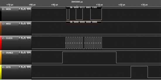
Dear TI Team,
I'm currently working on a redesign of a product using your DRV8823 to drive 3 DC motor actuated valves and 1 solenoid valve (old design used 2 L298 motor drivers). The new design also incorporates an SN65HVS880 input serializer on the same SPI bus which I already got working successfully.
Using the DRV8823 has been a bit more problematic, after a couple of days trying to troubleshoot it I think I'm at the point that I need your help. I'm managing to control each of the 4 bridges (getting +24V- 0 -24V as per my test routine) , but when I connect the motors the current gets limited to about 300mA, not enough to make the valves move. During normal operation one valve draws about 1.2A and takes only 1s to get from open to close position or vice versa.
I'm feeding 2.53V to the ABREF & CDREF pins through a voltage divider which is fed from the 5V supply of the SN65GVS880. The current sense resistors are 0.33ohms.
I've tried changing the 3 current regulation bits and other configuration combinations but to no avail. The test code which I'm currently using is posted below.
Any suggestions would be greatly appreciated.
Best Regards,
Loic
//DRV8823
// the motor driver communicates using SPI, so include the library:
#include <SPI.h>

const int csSrlzrPin = 8; //SN65HVS880 serializer CS, not used in this test code
const int loadSrlzrPin = 13; //SN65HVS880 serializer load pin

const int csMotorPin = 9; //DRV8823 CS pin
const int sstbMotorPin = 3; //DRV8823 sstb pin

const int channel = 1; //choose which motor channel we want to drive


int byte1 = B00011100; //initial state of DRV8823 control byte1
int byte2 = B00000111; //initial state of DRV8823 control byte2

void setup() {

  // initalize the load and chip select pins:
  pinMode(csSrlzrPin, OUTPUT);
  pinMode(loadSrlzrPin, OUTPUT);
  pinMode(csMotorPin, OUTPUT);
  pinMode(sstbMotorPin, OUTPUT);

  digitalWrite(csSrlzrPin,HIGH);
  digitalWrite(loadSrlzrPin,HIGH);
  digitalWrite(csMotorPin,LOW);
  digitalWrite(sstbMotorPin,LOW);

  // start the SPI library:
  SPI.begin();
  SPI.setDataMode(SPI_MODE0);
  SPI.setClockDivider(SPI_CLOCK_DIV16);		// Divide MCU clock (16MHz) by 16, SCK = 1MHz
  SPI.setBitOrder(LSBFIRST);
}

void loop() {

  driveMotor(channel, 1); //turn motor in direction 1
  delay(1000);

  driveMotor(channel, 0); //turn off motor
  delay(3000);

  driveMotor(channel, 2); //turn motor in direction 2
  delay(1000);

  driveMotor(channel, 0); //turn off motor
  delay(3000);

}


void driveMotor(int ch, int mode) {

  switch (ch) { //manipulate bits based on motor CH and direction commands
  case 1: //CH1
  if (mode == 0) { //Turns motor CH1 off
  bitWrite(byte1, 0, 0);
  }
  if (mode == 1) { //Turns motor CH1 on in direction 1
  bitWrite(byte1, 0, 1);
  bitWrite(byte1, 1, 0);


  }
  if (mode == 2) { //Turns motor CH1 on in direction 2
  bitWrite(byte1, 0, 1);
  bitWrite(byte1, 1, 1);
  }
  bitWrite(byte2, 4, 0);
  break;

  case 2: //CH2
  if (mode == 0) {
  bitWrite(byte1, 6, 0);
  }
  if (mode == 1) {
  bitWrite(byte1, 6, 1);
  bitWrite(byte1, 7, 0);
  }
  if (mode == 2) {
  bitWrite(byte1, 6, 1);
  bitWrite(byte1, 7, 1);
  }
  bitWrite(byte2, 4, 0);
    // statements
    break;

  case 3://CH3
  if (mode == 0) {
  bitWrite(byte1, 0, 0);
  }
  if (mode == 1) {
  bitWrite(byte1, 0, 1);
  bitWrite(byte1, 1, 0);
  }
  if (mode == 2) {
  bitWrite(byte1, 0, 1);
  bitWrite(byte1, 1, 1);
  }
  bitWrite(byte2, 4, 1);
    // statements
    break;

  case 4://CH4
  if (mode == 0) {
  bitWrite(byte1, 6, 0);
  }
  if (mode == 1) {
  bitWrite(byte1, 6, 1);
  bitWrite(byte1, 7, 0);
  }
  if (mode == 2) {
  bitWrite(byte1, 6, 1);
  bitWrite(byte1, 7, 1);
  }
  bitWrite(byte2, 4, 1);
  break;

}


//Transfer control bits via SPI to DRV8823


  // take the SS pin high to select the chip:
  digitalWrite(csMotorPin,HIGH);

  //  send in the address and control bits via SPI:
  SPI.transfer(byte1);
  SPI.transfer(byte2);

  // take the SS pin low to de-select the chip:
  digitalWrite(csMotorPin,LOW);

  //latch data from SPI holding register to motor control
  digitalWrite(sstbMotorPin, HIGH);
  delayMicroseconds(1);
  digitalWrite(sstbMotorPin, LOW);

}


