This thread has been locked.

If you have a related question, please click the "Ask a related question" button in the top right corner. The newly created question will be automatically linked to this question.

DRV8800 motor driver Current Limit Issue

My customer has the following question on a DRV8800 driver - can someone help address?  Thank you!

“I am driving a regular 12 volt motor that pulls 150mA when the motor is stopped. I have a 4.99 OHM resistor from SENSE to GND which would fault at 100mA according to the data sheet. As soon as I plug in the 12V it immediately faults and puts the motor into current recirculation and I am measuring on 74mV on the SENSE pin. I am wondering if the data sheet is wrong and the SENSE voltage is actually 50mV instead of the 500 mV they claim on the data sheet?”

  • When the sense voltage exceeds 500mV, the H-bridge is disabled.  The fault you're seeing might be due to VM undervoltage or overcurrent through the motor windings.  I suggest measuring the VM voltage during startup to see if it's stable.

    Best regards,
    RE

  • Response from customer:

    "The voltage on the motor stays at 12V. The comment makes no sense if you look at page 7 of the data sheet. It clearly states that SENSE will trip nFAULT. I have put a 10 OHM potentiometer on the sense resistor to try and adjust and cause a fault. When the SENSE voltage gets to about 175mV the motor Stops, The nFAULT goes low and there is 9.4 volts on OUT+ and OUT-."

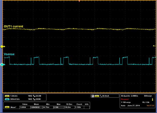
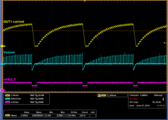
  • I took some bench measurements and confirmed that VTRP (the sense voltage trip) is indeed 500mV as the datasheet states.  These waveforms used a 0.2ohm sense resistor.


    You are correct that nFAULT goes Low when the sense voltage exceeds VTRP.  I suspected otherwise since the datasheet text doesn't mention that and most of our other devices don't behave that way.  I'm aware of Page 7, but "SENSE" there is vague, and the other acronyms "STB" and "STG" aren't defined anywhere else.  I'll add this to our list of improvements to make.

    Can you tell me what your input duty cycle is?  Can you capture waveforms with a current probe, and voltage probe on Vsense?  That will tell us more of the story.  By the way, I believe there is a 3us deglitch time applied to VTRP, where the sense voltage needs to exceed 500mV for more than 3us to be registered.

    Have you tried smaller values of Rsense, or removing it entirely?  It might be useful to first take fault out of the picture, and understand both startup current and input duty cycle versus current for your motor.  And then size Rsense appropriately.

    Best regards,
    RE

  • From customer:

    "Sorry it has taken so long to get back. I got hung up on a few other projects.


    The duty cycle is 100%. Right now we turn our motor one direction for 5 seconds then turn it the other for 5 seconds for testing. We do not have a current probe but I could send a scope shot of what Vsense looks like but I don’t understand the need. Our motor takes 45mA to run and 150mA when I manually stop the spindle from turning with a pair of pliers. I want it to stop at about 120mA. Using Ohm’s law this means I should only need a 4.17 OHM resistor between SENSE and GND. I have a potentiometer that can go from 0-10 OHM’s connected from SENSE to GND.


    What am I missing?"

  • Hi,

    It is worthwhile to determine the actual transient current during startup.  To do this, I would install a precise 1 ohm sense resistor and probe Vsense during startup.  The peak will determine (according to Ohm's Law, like you said) the maximum resistor value.  For example, if it peaks at 180mV using a 1ohm resistor, peak current is 180mA, and Rsense must be sized less than 2.7 ohms to keep Vsense < 500mV.

    Now, if running current is 45mA, startup hits 180mA (for example), and you want a trip point at 120mA, then you might want to limit the startup current by adding series inductance to the motor, for example.

    Best regards,
    RE