This thread has been locked.

If you have a related question, please click the "Ask a related question" button in the top right corner. The newly created question will be automatically linked to this question.

DRV8825 Current Glitch

Other Parts Discussed in Thread: DRV8825, DRV8711

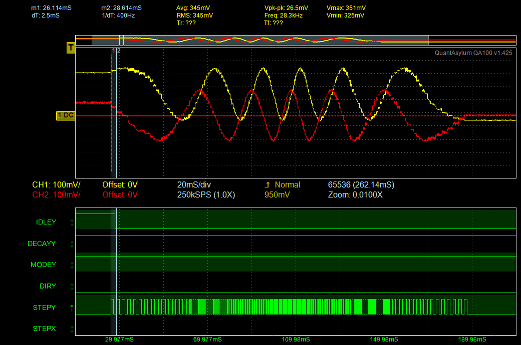
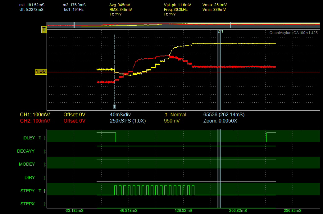
Hi, I'm having a problem with the DRV8825 that I don't understand. In the plot plot below, you can see phase A and B currents and also the step signals. The IDLEY signal isn't important. The DECAYY signal "high" means the HW is in mixed decay (floating pin). The MODEY signal is the MODE0 and MODE1, and MODE2 is tied low (which means this is 1/8th step mode). StepY starts at 400 Hz pulse rate, speeds up and then slows down.

So, the summary for this first plot is that things seems reasonable and the motion sounds/feels/looks smooth.

The problem I'm facing is that for single or double 1/8th stepping the steps are nowhere near close. There is a big step that sounds like a clunk, and then very faint ticks. The clunk definitely moves the shaft, the ticks are much smaller moves. The patterns seems to be CLUNK tick tick tick tick CLUNK tick tick tick. 

Looking at a tick (slight move, about what I'd expect) I see the following:

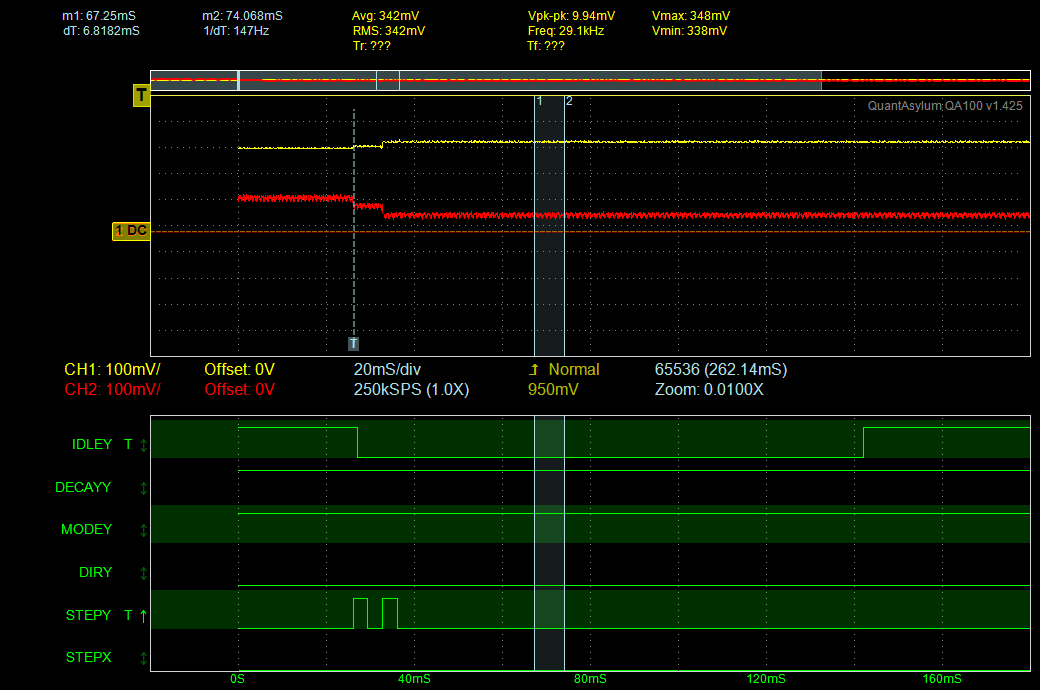
In the above, note there are two discrete changes in the phase currents. Makes sense. Feels right. But every 4th movement there is the clunk (bigger jump), and here is what that looks like:

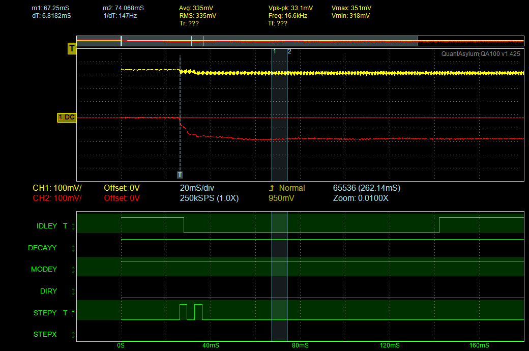
Note the yellow phase current again exhibits two discrete steps, but the red phase current has a sloppy transition through its step and then moves to a totally unexpected value.

Now, back to a variation of the first capture: If you look closely, the bigger moves will also show regions of this strange behavior. In the capture below, you can see it marked during the slowdown (red trace), but you can also see it in the yellow trace during the acceleration. 

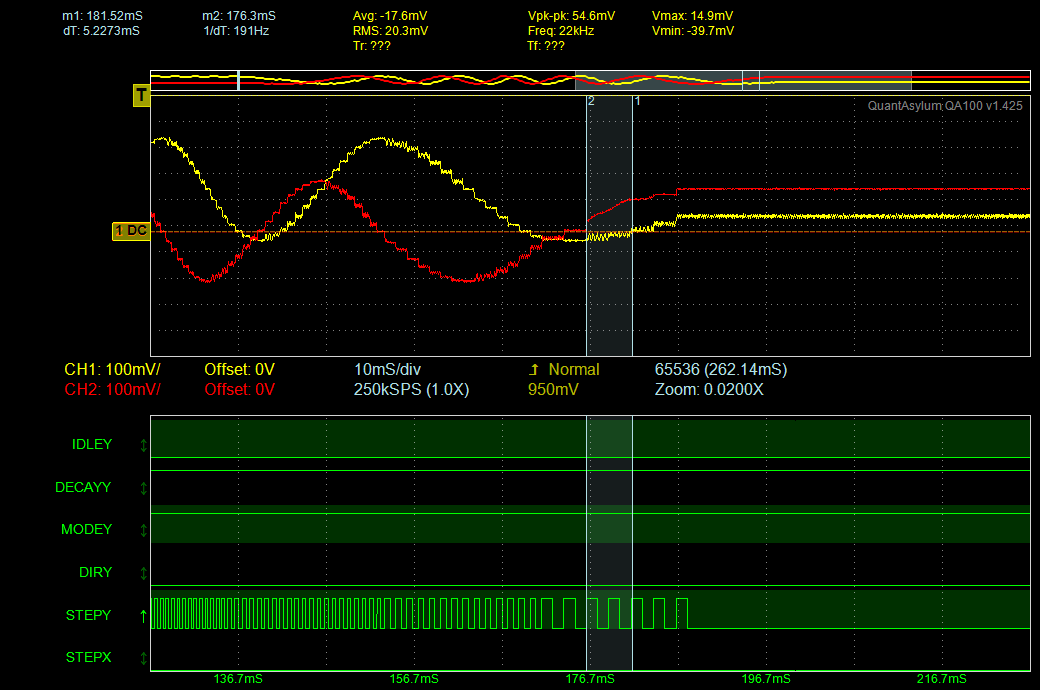
And one more weird one:

Any idea on what might be going on? TIA for any insight.

  • SeattleEE,

    Let me first explained my understanding from the waveforms. Once we agree on this and come to same understanding, I would be able to help with root-cause of the issue.

    Below are my observations:

    1. Every time if previous step current level is near zero, current fall or rise are steep (higher than expected step value).
    2. Current rise or falls are more prominent if step frequency is slow, during acceleration/ deceleration phase. As step frequency becomes high, step distortion also reduces, in-fact not visible much when motor is running at continous high step frequency.

    Let me know your feedback.

    Best Regards

    Milan-Motor Application Team

  • Here is one more datapoint: If I set the mode to fast decay, it works as expected. By sending single or double pulses to the controller, I see the current levels track the table 2 values for winding current. But if I'm in mixed decay, then sending single or double pulses to the controller can show big skips in the table at certain points. 

    Searching on the forum for "mixed decay" I've seen other places where people comment on rough/jerky movement in mixed mode. 

    My question at this point is this: Why does mixed decay not follow table 2? The 3rd plot I posted is a very good example of this: The red phase current jumped from 0% to almost -100% of max current in two steps. Why? That seems impossible from the table 2 description. It should have jumped from 0% to -20% to -38% while the other winding went from 100% to 98% to 92%.

  • Hi SeattleEE,

    Please note the last paragraph of  section 8.3.3 in the datasheet, which states:

    Mixed decay mode begins as fast decay, but at a fixed period of time (75% of the PWM cycle) switches to slow
    decay mode for the remainder of the fixed PWM period. This occurs only if the current through the winding is
    decreasing (per the indexer step table); if the current is increasing, then slow decay is used.

    When the absolute value of the current increases from the prior step, the controller runs in slow decay. Some motors operate properly when using slow decay when increasing and mixed decay decreasing. Other motors experience loss of current regulation, which appears as large jumps that do not correspond to the step table.

    Fast decay creates more current ripple but follows the step table.

    You also may find that mixed decay works better as the speed of the motor increases. It is possible to change on the fly. For slow speeds, fast decay may be needed and then as the motor speed increases mixed decay can be potentially be used.

    The DRV8825 provides the ability to tune the motor being used.

    The following application note provides a little more detail about the decay modes: http://www.ti.com/lit/pdf/slva321 Figure 7 shows how mixed decay works.

  • Thanks very much, this is very clear. I've read through the app note you reference a few times over the last year or so. I'll note that the TI docs are very good at explaining how the various modes work, but there's not much explaining when to use the various modes, and pluses and minuses of each, etc. Your 3 paragraphs above are very valuable in helping to understand when to use each.

    I'm going to the update the FPGA as follows:

    In stepper hold mode, use slow decay to help with noise.

    When accelerating/decelerating and at slow speeds, use fast decay to ensure the expected current waveform is tracked.

    For fast movements, is there much benefit to using mixed over fast decay? Maybe a little better with noise I suspect, but anything else you can think of?

    Thanks again for your valuable insight. 

  • SeattleEE said:
    For fast movements, is there much benefit to using mixed over fast decay? Maybe a little better with noise I suspect, but anything else you can think of?

    There can be benefits depending on the step speed. The goal is to reduce the current ripple, which has the primary benefit of higher torque (higher average current).

    I also forgot to mention the application note for the DRV8711 http://www.ti.com/lit/an/slva637/slva637.pdf This app note shows the benefits of various decay modes and the effects of tuning the blank time, off time, and fast/slow decay ratio when in mixed decay. The DRV8711 has many more control knobs than the DRV8825, but the basic concepts are the same.

    Please note section 5, which appears to be an exaggerated version of the slow/mixed decay you see. For the DRV8825, the fix for a current distortion like this one is the use of fast decay. 

  • Understood, thanks. The DRV8711 spec is very good. 

    BTW, the DRV8825 when idle in slow decay tends to thermal fault a lot. But in fast decay that doesn't happen. Is this because the slow decay is recirculating through the lower mosfets creating more i2r loss, while fast decay just dumps it out to the supply?  

    For my own future reference (and anyone else that stumbles on this post):

    Slow decay benefits: Reduced noise, less ripple in current waveform resulting in slightly higher RMS currents (and thus torque) compared to fast decay.

    Slow decay drawbacks: Increased thermal load on driver, can run into issues following target indexer waveforms based on certain L/R combinations, which means stepper position can momentarily lost and/or steps lost. In the case above, microsteps became erratic and uneven. 

    Fast decay benefits: More precise positioning, especially at slower speeds, since stepper can be made to precisely conform to stepper index table, more forgiving thermal design. In my particular case in some quick trials with heat gun, I'd guess I have 15 to 20 degree more ambient margin in fast versus slow. Slow decay at room temp with no motion faults every 10 to 15 seconds. Fast decay at 35'C with no motion never faults. 

    Fast decay drawbacks: Higher ripple currents can lead to unwanted noise, slightly reduced overall torque due to reduced RMS currents. 

    Feel free to correct my generalizations as needed. And again, thanks to TI for the help here.