This thread has been locked.

If you have a related question, please click the "Ask a related question" button in the top right corner. The newly created question will be automatically linked to this question.

DRV2700 Reference Design (+/-200V)

Other Parts Discussed in Thread: DRV2700, DRV2700EVM

Hello,

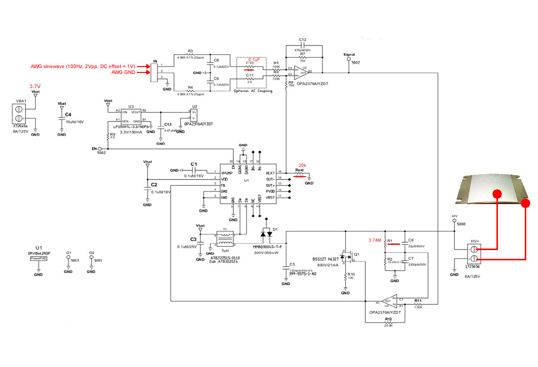
We made a board based on Brian Burk's DRV2700 Reference Design design:

"DRV2700EVM-HV Reference Design - 2014-06-19.pdf"

Our board + BOM matches the DRV2700 Reference Design design exactly. The board works; however...

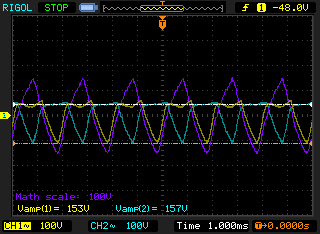
We want to get 400V AC output (+/-200V).  Is it possible with the existing circuit ?

If not, what can we change to accomplish this ?

Thank you !

5557.DRV2700EVM-HV Reference Design - 2014-06-19.pdf

  • Hello Paul,

    The design you mentioned can only go above ground. However, if you use another one of these same boards and instead of referencing to ground you reference to the other board's high voltage output, then it is achievable.

    So using two boards, tie your load between HV1 and HV2 and then drive them out of phase such that your total output voltage will be HV1 - HV2. Therefore when:

    • HV1 = 200 and HV2 = 0 --> HV1 - HV2 = +200V
    • HV1 = 0 and HV2 = 200 --> HV1 - HV2 = -200V

    I hope this helps and let us know if you have any additional questions.

  • Hi Rodney, thanks for the fast reply.

    I ran a 2-board test with the following connections:

    VBAT <- 3.7V
    PCB1.IN1 <- sinewave (500Hz, 3.7Vpp)
    PCB1.IN2 <- GND
    PCB2.IN1 <- GND
    PCB2.IN2 <- sinewave (500Hz, 3.7Vpp)
    PCB1.HV -> scope.CH2
    PCB2.HV -> scope.CH1

    My output is shown on the attached scope capture.  Seems promising, but I have some questions.

    1)  What's the max voltage for VBAT ?
    2)  What's the max amplitude (pp) for my input sinewave ?
    3)  What DC Offset to use for my input signal ?

    As mentioned we'd like to get +/-200V (AC output).

    Thanks again !

  • Hello Paul,

    Looks like you are able to get +/-200V, so we are getting close.

    To answer your questions:

    • VBAT can go to 5.5V, however we have seen based on the transformer that you might need to increase the current limit by changing Rext.
    • Usually, we float IN+ so that it stays at Rext voltage. Then IN- can go below and above it. Since you are grounding IN+, you can try taking IN- to the Vdd of the opamp.
    • If you keep the one terminal grounded then you would want your DC offset to be half your swing so that you stay above GND.

    Based on this, I would try it without grounding the inputs and instead let them float at the Rext voltage. Also, I have a few questions too:

    • Have you tried slowing the frequency down to see if it goes higher?
    • It looks like your outputs are going -100V which doesn't make sense to me. Is your scope AC coupled?
    • If you just control one of the boards, how high does the output go?

    Let me know.

  • Rodney, we made some progress but now have more questions...

    I changed  C10  to 0.1uF (coupling cap) and now get +/-200V with one board (going to my scope, AC coupled):

    IN1 <- sinewave (100Hz, 2Vpp, DC offset = 1V)
    IN2 <- GND

    However, when I add my load (LI-1 actuator, datasheet attached) the output drops **way down** to approx +/-12V:

    HV+ -> actuator top
    GND -> actuator bottom

    Why does the output voltage drop so far ?  Is the current limit (REXT = 20k) set too low ?

    What do you recommend I try, so I can drive the actuator at +/-200V ?

    Thank you !

  • P.S. The attachment didn't work for some reason, so here's a link to a **similar** part:

    http://www.faceco.com.php53-6.dfw1-1.websitetestlink.com/Face%20International/6r-ds.pdf

    My actuator's specs are below:

    Capacitance = 75nF
    Max Voltage = +/-240V
    Mass = 5.7g
    Footprint = 45.47mm x 39.19mm
  • Hi Paul,
    Your load of 75nF doesn't sound too high. You can try increasing the current limit as you mentioned to see if that will help. To make sure we aren't lost in each others descriptions, can you post your circuit schematic with proper labels of the inputs and outputs? I think once I have that it will be much easier to help.
  • Rodney,

    Here's our schematic with inputs + outputs labled in RED.

    It matches your design exactly aside from a few values, also noted in RED.

    Please see my last post for a description of the problem.

    Thanks !

  • Hi Paul,
    Sorry for the delayed response. Based on your circuit, try floating pin2 of the input to bias it at Rext instead of 0.74V at the input of the opamp. Additionally, you can tune the input signal from 2Vpp while keeping the offset at 1.3V (VRext).
    Hope this helps!
  • Rodney,

    When I float PIN2 of the input, my scope output goes down to +/-75V.  It's +/-200V when Input.PIN2 = GND.

    Can you please explain what's meant by "tune the input signal from 2Vpp while keeping the offset at 1.3V" ?

    My problem remains the same (see post dated "Jan 3, 2015 9:53 PM")  =>  how to drive my actuator at +/-200V.

    Thanks !


  • Hi Paul,

    Just to be sure, you have the piezo biased between two boards with the piezo going to each of the HV outputs, correct? (not to a single board as you have drawn)

    Additionally, did you try raising the current limit? We have seen the boost feedback falsely trip and cause the transformer to not build up energy if the current limit is set low enough. (This would result is a lower boost voltage)

    For reference, I put 154nF on the ouptut of a single board (same output architecture) and was able to just barely get 200V (started peaking) at 100Hz.

    If the current limit doesn't help, feel free to send me an email message and we can figure this out off of the forum and then just post the solution.


  • Rodney,

    I'm using a single board exactly as shown in my "Jan 7, 2015" post.

    I haven't changed REXT (it's still 20k). What value do you recommend, given my 75nF load ?

    Thanks again
  • Hi Paul,

    As I mentioned in a previous post on Nov 19, 2014 5:35 PM, you will need to have a second board to get a differential negative voltage (see the post for more details). See attached picture for a diagram.

    Also, you should be ok to change the Rext to 15k if needed.

    Hope this helps.


  • Hi Paul,

    I just wanted to mention that the DRV2700 is now released and can be found online.