This thread has been locked.

If you have a related question, please click the "Ask a related question" button in the top right corner. The newly created question will be automatically linked to this question.

DRV8823 vs DRV8824

Other Parts Discussed in Thread: DRV8823, DRV8821, DRV8823EVM, DRV8821EVM, DRV8824

Hello,

Recently bought a DRV8823 EVM seeing its capability of driving two motors simultaneously. But after looking into DRV8821, I just came to know that DRV8821 can also do the same.

I have the following queries. 

Please clarify me.

1. Is the major difference of drv8823 over drv8821 is its serial interface for data communication?

2. Is inbuilt micro-stepping available only with drv8821?

3. Does the 3-bit winding current control via register setting in drv8823 does the same function as that of micro-stepping indexer in drv8821?

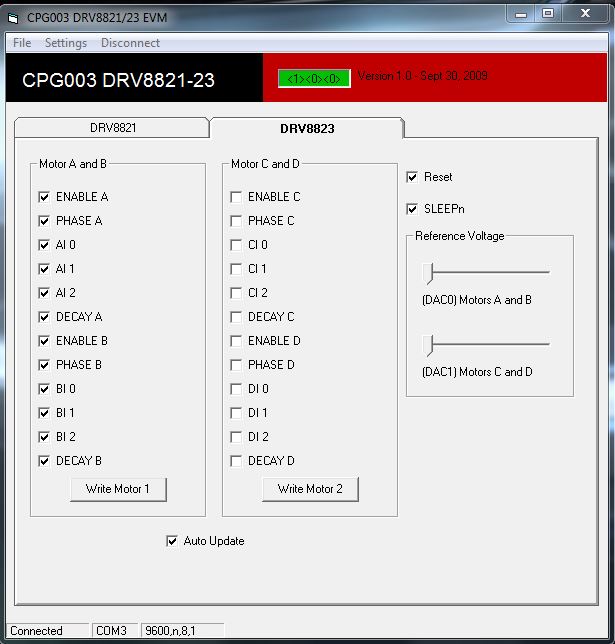
4. The evaluation module has two separate windows for drv8821 and drv8823. There are speed control options available with drv8821 for both AB and CD motors. Can the same options be used if we have a drv8823 module?

 Thanks in Advance.

  • Hi Siva,

    1. Correct, these devices are similar power stages with different interfaces.

    2. Correct, the indexer is only on the DRV8821.

    3. The DRV8823 still has a 3 pins (xI1, xI2, xI3) which control the current regulation level. These can be used to implement microstepping for this device, it will just need to be managed by the controller. You can follow the indexer tabler provided with the DRV8821 to implement the same microstepping scheme.

    4. We only provide the speed control code for the DRV8821 firmware. We just provide simple control of the DRV8823. You would have to write your own code for speed control using the DRV8823.

  • Hi Nick,

    Thank You for your valuable response.

    From your reply I understand that there is only simple control for DRV8823 EVM, which can allow only rotation of motor.

    In this case what would be the default speed of rotation and default direction of rotation?

    I have inserted the snapshot of the DRV8823 EVM GUI. I have connected a 0.8A stepper motor. My Vref calculated was 4.24V which I have given externally (as the EVM POT limitation is 3.3V and DAC POT limitation is 2.5V)

    My stepper motor is not rotating and it gets heated up!!!

    Please help me with your expertise.

  • Hi Siva,

    The motor will not rotate as the current is not changing in the phases. The DRV8823 GUI allow for simple ON/OFF control of the H-Bridges to evaluate them. You would need to write your own firmware to modulate the current in the proper sequence for stepper rotation.

  • Hello Nick,

    So, now I understand that the DRV8823 EVM is capable of just ON/OFF control at the Motor Output ports. So what is the use of this evaluation board (DRV8823 EVM) ?

    Is DRV8821 EVM and its supported software capable of rotating motor, speed control and step control?

    Also what is the difference between On-chip microstepping and other 1/X microstepping techniques?

    My application has two stepper motors (1.5 A and 0.8A). The span of 1.5A motor is to rotate +/- 10deg and the span for 0.8A motor is to rotate +/- 20deg. Initially I need to interface the motor to the driver and do some reverse engineering in laboratory where we will understand the step angle and step size required to obtain certain functions of the application. I don't prefer to write any firmware as I am not good at it.

    So decided to go with the available EVMs but 8823 EVM is now understood that it is not capable for what we are expecting. So confused between 8821EVM and 8824EVM because of the different indexing options (On-chip microstepping and other 1/X microstepping) that they have.

    Please guide me further.

    Thanks in advance.

    Regards,

    Siva

  • Hi Siva,

    Sorry for the confusion. The DRV8823EVM would be to evaluate some of the simpler functions of the device. Most would then move to their own PCB for more indepth testing.

    The DRV8821EVM does provide support for a basic stepping profile.

    On chip microstepping (DRV8821) takes the microstepping (indexer) table and moves it into the motor driver. The motor driver then moves through the table on each rising edge of the STEP input.

    With external microstepping (DRV8823) the motor driver provides all the functions for microstepping (current regulation, current step levels, etc.) but does not have the microstepping (indexer) table in the digital logic. It requires an external controller to move through the proper microstepping sequence.

  • Dear Nick,

    Thanks for your constant support as always.

    Now switched to DRV8824. 

    I have built a circuit for its operation refering to the schematic.

    Even now, the Motor output pins (AOUT1 & AOUT2, BOUT1 & BOUT2) stays constant at Motor operating voltage (11.98V)  and there is no change in phases.

    I have not used any controller. Following are the input details:

    MODE0: HIGH

    MODE1: HIGH

    MODE2: HIGH

    nENBL: LOW

    DIR: OPEN

    DECAY: HIGH

    nRESET: HIGH (Motor output goes low when kept low)

    nSLEEP: HIGH (Motor output goes low when kept low)

    AVREF: 3.5V

    BVREF: 3.5V 

    STEP: 2Hz input, 50% duty cycle. (Verified 2 Hz input to DRV)

    GND is not making any difference to motor output pins, the Motor coil outputs are held high even when GND is left unconnected. (Both GNDs)

    RSENSE: 0.8ohm

    a 0.01 microfarad capacitor between CP1 and CP2

    a 0.1 microfarad capacitor between Vm and VCP, but had not connected a 1Mohm resistor parallely (Is this a reason that the outputs are always held high?)

    Stepper motor is a 0.8A motor.

    Kindly help me where I had gone wrong..

    Thanks in advance.

    Regards,

    Siva

  • Hi Siva,
    Can you clarify. We have been discussing DRV8821 vs DRV8823. Are you now using DRV8824?
    Can you provide the schematic so I can look it over. After I review the schematic I can ask you to check a few different things.
  • Hi Nick,

    Yes, currently working with DRV8824. But not with the EVM, only with the driver IC.

    I am using the same schematic used in the TI reference design.

    My stepper motor rating is 0.8A, I don't have any datasheet of the motor and not available online also.

    It has a phase resistance of 15ohm, so I concluded its Current rating to be 0.8A knowing its operating voltage to be 12V. 

    I don't have any data on the step angle also.

    Wiring has been done as per the schematic and data sheet.

    I have not used any controller. Following are the input details:

    nENBL: LOW

    DIR: OPEN

    DECAY: HIGH

    nRESET: HIGH (Motor output goes low when kept low)

    nSLEEP: HIGH (Motor output goes low when kept low)

    AVREF: 3.5V

    BVREF: 3.5V 

    STEP: 2Hz input, 50% duty cycle. (Verified 2 Hz input to DRV)

    GND is not making any difference to motor output pins, the Motor coil outputs are held high even when GND is left unconnected. (Both GNDs)

    RSENSE: 0.8ohm

    a 0.01 microfarad capacitor between CP1 and CP2

    a 0.1 microfarad capacitor between Vm and VCP, but had not connected a 1Mohm resistor parallely.

    What should be the STEP input frequency and its Vp (Peak Amplitude)?

    MODE2=HIGH, MODE1=LOW, MODE0=HIGH

    There is phase change according to the STEP frequency, when the frequency is kept low at 2Hz it takes larger time for phase change and when the frequency is increased to 20Hz there is a faster phase change.

    But the motor is making noise when connected to output pins and its not rotating.

    Kindly help me where I had gone wrong..

    Thanks in Advance

    Regards,

    Siva

  • Hi Siva,
    It would be good to triple check all connections and with another motor. Do you have the motor phases connected correctly? How are you connecting to the DRV8824. Have you designed a PCB or are you using some sort of breakout board. Introducing a large inductance in the SENSE line could throw off the current regulation.
    The STEP frequency is dependent on the motor paramenters and your application requirements. The DRV8824 supports anywhere from 0 to 250kHz. Can you obtain a scope capture of the STEP input and motor current waveform?
    Vp for the STEP signal is a logic 3V or 5V.
    The current magnitude should change according to the STEP input so this makes sense.
    It sounds like the device is functioning but something is not connected correctly.
  • Try going to a larger microstepping level. 1/4 or 1/8.
  • You should also try and find a datasheet for the motor. Generally the short circuit current is not the same as the rated current for the motor.