This thread has been locked.

If you have a related question, please click the "Ask a related question" button in the top right corner. The newly created question will be automatically linked to this question.

DRV8432 Failures

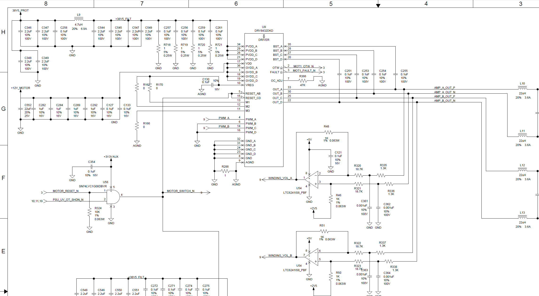
We are using 2 DRV8432s to drive 2 stepper motors.  We are experiencing random DRV8432 failures resulting in a dead short between PVDD and GND.  The output that fails is always random as is the IC.

PVDD = 38.5V

GVDD = 12V

Any ideas what could cause this?  It seems to occur on power down, but I have yet to verify this as this failure occurs extremely infrequently.

  • Hi Chris,

    The failure described can be a result of violating the absolute minimum/maximum voltages of the device. Can you take a look at voltage excursions during the power down?

    Can you provide more information such as
    1) How is the device powered down (outputs enabled/disabled? If enabled how much current?)
    2) Schematics/layouts
    3) Screen shots of the device PVDD and GND pins during the power down sequence
    4) Any additional information related to the failure described
  • Schematic attached -  it's very similar to the reference design.

    There is no special power down sequence.

    TI investigated some of the damaged parts we had and came to the conclusion that they died as a result of an electrical over stress event.  I'm not seeing any glitches - certainly nothing that would cause a part capable of 70V part to fail.

    Our failures are so infrequent, it's extremely hard to instrument up a scope to capture the failure.  The likely hood of capturing the fault are low.

    Any other idea?  I'll keep testing on my end...

  • Hi Chris,

    There are a few questions from the schematic.

    Is there a larger bulk capacitor for PVDD somewhere? I see only about 20uF on PVDD.
    Is it possible to get the layout?
    Can you confirm the PWM frequency?
    How many devices failed and how many were tested?

    I will also try to contact the people who evaluated the damaged devices to determine if they can help.
  • Each board has 2 motor drivers - the attached circuit is essentially duplicated.  Other than that, there is a small amount of capacitance, roughly 60uF elsewhere on that rail.  Total capacitance on the 38V rail would be around 100uF.  That said, our LRU is powered via another LRU so the majority of the hold up capacitance is contained within the other LRU.  

    PWM frequency is 412KHz.

    I can send the layout - what is your email address?  The board is 14 layers, so it's not super straightforward to post here.  If I just send the gerbers you're going to have a hard time figuring out which net is which.  Board was done in Mentor graphics.

    We've had 5 or 6 ICs die out of a total of 45 boards with 2 motor drivers per board.  A single board ate 3 parts in fairly quick succession, always the same IC, but different outputs would fail.  I was never able to capture the failure with a scope as the failure ceased to occur.  

  • Hi Chris,

    We have a few more questions that we hope can lead to the root cause:

    1) Can you describe what type of testing the devices are being subjected to?
    a) Are there any specific tests that seem to create the failure?
    b) What tests are hard on the system, such as stopping the motor suddenly or turning the system off while running at maximum current?


    2) What is the current rating of the 12V supply for GVDD and VDD?
    A recent update to the datasheet recommends 5-10% of the load current with a minimum of 100mA. Please refer to section 8.2.1.2.2 of the most current datasheet. It should state DRV84x2; there is a typo. If the 12V droops, it may exceed the absolute maximum ratings as it recovers. Please take a look at the inputs to these pins also.
  • I have noticed a large amount of current is passed back through the DRV8432 IC and can be seen on the PVDD rail when power to the entire board is shut off. The inertia on the motors is momentarily turning the IC into a generator . Is this expected behavior?
  • Hi Chris,

    Yes, unfortunately the current in the windings has to go somewhere in this condition.

    As the system powers down, typically the only place for the current to go is through the body diodes of the DRV8432 and into the bulk capacitors on PVDD. The body diodes are designed to handle the current, but if the bulk capacitance is too small the voltage will spike.

    For more information please see ( LINK )This was written by a member of the team and describes what can happen.

  • Rick,

    I've spent the past few days investigating this further.  

    As you predicted, we are getting a short duration, 100uS, voltage of spike between 5-10V; however, the circuit monitors the PVDD voltage, when it drops below 26V, the motor driver resets are pulled low - this is the point at which the voltage spike occurs - so even though we have a voltage spike, the PVDD rail is only at 26V at that point.  We would need a 25V+ voltage spike to even come close to exceeding the rating of the part.  Even with motor motion and worst case current draw, I don't see a voltage spike anywhere near 25V.  I think we can rule this out as the failure mode.

    That said, as soon as the PVDD rail drops below 26V and the reset pins on the motor driver are pulled low, the resultant voltage spike exceeds the hysteresis of the UV circuit and the motor driver resets are pulled high again momentarily.

    Assuming the PWMs are operational, the voltage rails are sufficient to drive the motor driver, could glitching on the reset line cause the internal H-bridges to be damaged?  

  • Hi Chris,

    Thanks for looking into this. I agree it does not seem to be a PVDD spike causing the failure.

    Glitching on the reset line should not cause damage, though it can cause voltage spikes similar to those experienced when the outputs are disabled.

    Did you get a chance to look at VDD and GVDD also?

    In a prior response it was noted:

    2) What is the current rating of the 12V supply for GVDD and VDD? 
    A recent update to the datasheet recommends 5-10% of the load current with a minimum of 100mA. Please refer to section 8.2.1.2.2 of the most current datasheet. It should state DRV84x2; there is a typo. If the 12V droops, it may exceed the absolute maximum ratings as it recovers. Please take a look at the inputs to these pins also.


    This still needs to be ruled out.

    Thanks.

  • We have 2 motor drivers running off the same 12V regulator, total current consumption is typically around 100mA. I'd have to talk to the power supply designer, but I believe there is a lot of headroom on that rail.

    The GVDD/VDD rail has essentially no voltage spikes on it - it looks clean and we keep the voltage between 11.5 and 12.5V.