This thread has been locked.

If you have a related question, please click the "Ask a related question" button in the top right corner. The newly created question will be automatically linked to this question.

DRV8332 Low Side Shutdown

Other Parts Discussed in Thread: DRV8332

Hello,

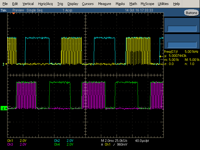
I'm using the DRV8332 to drive a BLDC motor using non-complimentary control. We PWM the driving phase and hold the other phase low. This works well most of the time but when the duty cycle begins to increase due to motor loading we see a state in which the high side is still PWM-ing however the other phases are in high impedance. It seems as if the low side FET is not on therefore the current stops and the motor stalls. Here is a plot of the phase outputs during a stall. 

C1= Phase A, C2= Phase B, C3= Phase C, C4= 12V supply for GVDD. 

During this conditions the FAULT line never goes low and the 12V supply is solid. The OC_ADJ resistor is 20K and is set for CBC current limit. The datasheet says " If you prefer PWM switching one channel but hold low side FET of the other channel on (and third channel in Hi-Z) for 2-quadrant mode, OT latching shutdown mode is recommended to prevent the channel with low side FET on stuck in Hi-Z during OC event in CBC mode."

The motor current doesn't seem high enough to trigger the current limiting feature but the low side FET stuck in HI-Z seems to be what I'm seeing. Can you explain what is happening and what I can do about it?

Regards,

Mike


  • Hi Mike,

    It is possible that you are experiencing an OC event, as described in the 3rd paragraph of page 12.

    It is important to note that if the input to a half bridge is held to a constant value when an over current event occurs in CBC, then the associated half bridge will be in a HI-Z state upon the over current event ending. Cycling IN_X will allow OUT_X to resume normal operation.

    In the event described above, the FAULT signal will not go low.

    Please try cycling the output stuck in Hi-Z to determine if it recover. A small high pulse (50 to 100ns for example) at the end of the PWM cycle is generally all that is required.
  • Mike, depending on the measurement technique, the actual current might be higher than what you measured. Using a current probe around a phase wire is typically reasonably accurate.

    You could try setting OC latching mode, and verifying you get a latched shutdown. That would further confirm you're hitting OC. Or also try reducing OC_ADJ resistance.
  • Rick,
    Thanks for the response. This appears to be what is happening. We added a 100ns "un-latch" pulse on every cycle and the system performs nicely now.

    Regards,
    Mike
  • Mike,

    Glad to hear it is working. Let us know if we can be of further assistance.
  • I'm having a similar issue. Should this reset pulse be applied to the PWM pin or RESET pin of the half-bridge that went into a HI-Z state?

  • Hi Robert,

    The pulse should be applied to the PWM pin.
  • Hi Rick,

    The PWM input signal is continuously pulsing high and low, once every cycle. Why that isn't enough to cause a reset? Thanks.
  • Hi Robert,

    Are you all PWM'ing all outputs that have current flowing through them? If not, the half bridge with a static input could have sensed the OCP and turned off.

    It will not recover until the static input is pulsed.

    If that does not work, please send scope captures of the inputs and outputs.
  • I'm using a modified version of the TI BLDCPWM_DRV macro to do PWM and commutation.

    Here is a capture of the inputs PWM_A, RESET_A and PWM_B, RESET_B. Phase C is not shown due to lack of scope channels but looks normal.

    Here is a capture of the motor phase voltages. 

    Motors are operated in PID velocity mode. The motors are required to do a lot of starting, stopping and reversing direction. The faults seem to happen mostly at startup and stop when commanded to go at high speed. The faults will occasionally cause a motor to fail to get moving but will recover when direction is reversed.

  • Hi Robert,

    I am assuming channels 1 and 2 are superimposed and channel 1 is PWM_A and channel 2 is RESET_A. Same for channels 3 and 4.

    Using the left side of the scope capture as time 0, PWM_B is pwm'ed while PWM_A is held low and RESET_A is held high from time 2.3ms to 3.7ms. If an overcurrent event is detected on OUT_A during this time, OUT_A is disabled. Current will not flow until either RESET_A is toggled or PWM_A is toggled.

    I was not clear earlier. You should PWM both PWM_A and PWM_A in the scope capture that you have provided. A small high pulse of 50 to 100ns on PWM_A at the end of every PWM cycle should clear this up.

    For additional information, please see the third and fourth paragraph of section 8.3.2.1.1