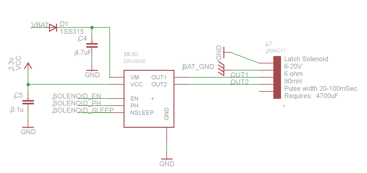
Good day,
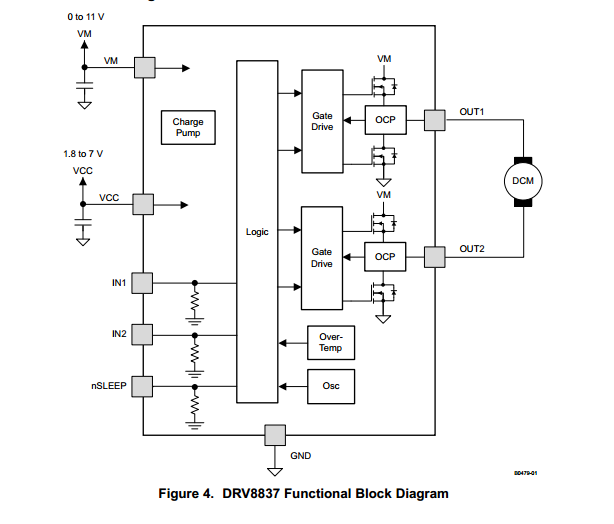
Included here for convenience is my schematic and the functional block diagram from the DRV883x data sheet. Battery voltage (V_BAT) is 7.2v. I am driving a solenoid R-L-C circuit. The inductor and resistor values are stated in the solenoid's data sheet as 90mH and 6 ohm respectively. It is also stated to require a 4700uF capacitor in series with the solenoid. I assume because the reactive values cancel out. Expected current is to peak at 1.2A. The result is that the circuit is under damped at approximately 0.69.
Looking at the function block diagram it appears that the output is not isolated from the input. Does this not mean that the current that flows through the output pins must come from and return to my battery source?
I ask this because it states in the DRV883x data sheet that the operating current I_vm = 0.1mA max at V_m = 5v; Vcc = 3v with No PWM.
http://www.ti.com/lit/ds/symlink/drv8838.pdf
Also, if I may ask here. Would it not be beneficial for me to calculate a value of capacitance that is closer to critical damp? At 0.69 damp I expect the transient waveform to dip below reference causing a reverse current.