This thread has been locked.

If you have a related question, please click the "Ask a related question" button in the top right corner. The newly created question will be automatically linked to this question.

DRV8825 + NXP PCA9629

Other Parts Discussed in Thread: DRV8825, DRV8846, DRV777, DRV8803, DRV8848, DRV8833, DRV8825EVM, DRV8834, DRV8711, DRV8841, DRV8843

Hello!

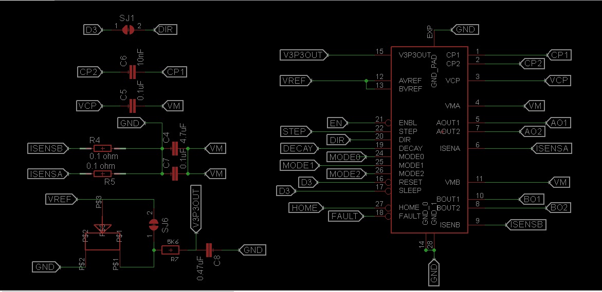
Can  PCA9629 is able to drive the DRB8825? I can see that PCA9629 can drive the H-BRIDGE directly but DRV has it's own logic to generate the pulses for the internal  bridge.

My idea is to use one of the "OUT0" to "OUT3" pin from NXP to send pulses to the STP pin of DRV8825, the DIR pin doesn't matter because the stepper is used only in one direction.

Data sheet:

Thanks!

  • Hi Lucian,

    The PCA9629 is not required to drive the DRV8825. A mcu with the ability to provide a step pulse at a specified rate is required.

    The DRV8825 contains the logic required to drive the stepper motor. Controlling the stepper motor requires setting up the configuation pins, enabling the device and sending a step command to advance the motor.

    What are the voltage and currents you plan to use? Other DRV8x devices, such as the DRV8846 may be a better fit if your system voltage is low enough.
  • Thanks for the replay!

    My problem is that I'm using the i2c bus on Raspberry Pi to comunicate with the motors.
    With so many devices connected on the i2c bus it's difficult to send pulses to lets say 5 steppers on the same time because RPI has only 100 k bus speed. The downside is that the steppers speed is decreasing because of the bus limitations
    Baisicaly i need some ic that works on i2c bus to drive the Ti DRV.
    The motors voltage will be between 4-12v, anyway i will chose the motors that fits the driver.
  • Hi Lucian,

    If the motor voltage is < 20V and the current is < 140mA per coil, please look at the DRV777. (3) DRV777 could possibly be used to control the 5 steppers. The OUTx of the PCA9629A would be connected to the inputs of the DRV777.
  • Motor current will range between 0.5 to 2 amps.
    In the pca9629 data sheet at page 37, 38, 39 logic output sequence it's shown, the question is:
    What pins i need to connect not to lose any steps that PCA is outputing?
    Thanks!
  • Hi Lucian,

    At that current, the DRV777 will not work. The DRV8803 may be the best fit from the information provided, although it is at the top of the current rating. If you are not using the 2A for long periods of time, it may work. This assumes that you have at least 8.2V to supply the DRV8803 and the PWP thermally enhanced package is used.

    The benefits of using a device like this is the built in protection, such as over current protection, short circuit protection, under voltage
    lockout and overtemperature.

    The inputs of the DRV8803 would be connected directly to the outputs of the PCA9629.
  • I think i'll be using this motor along with a 12v psu and DRV8803, do you think it's ok considering that DRV doesn't have a current limiting circuit?

     Motor specs:

    Rate Voltage - 4.16

    Rate Current - 1.3

    Phase Resistance ( Ω ) - 3.2

  • Hi Lucian,

    Since there is no current limiting circuit, extra care must be taken to ensure the motors are not damaged. If the DRV8803 outputs are unintentionally activated, there could be as much as ~4A through the motor (12V/3.2 Ohms).

    The simplest method is to set another power supply to approximately 4V. This will limit the current to the rated amount automatically.

    Next would be PWM'ing the inputs of the DRV8803 to limit the current. But, the PCA9629 does not appear to have the ability to PWM its outputs. So it appears you are limited to lowering the voltage at the motor.
  • Using a 5v power supply will deliver +0.26 amps current to the motors, but again the DRV8803 doesn't work below 8v. I'm also thinking on a pairing two dual bridge fets (space saving)  to make a H Bridge, any ideea about one that works with 5v output?

  • Hi Lucian,

    There are plenty that work at 5V. Here is a list of several ( LIST ). This are dual, some have a common source to reduce pinout.

  • I think i've found a suitable IC ... DRV8848.
    What's Your Opinion on this one?
    Btw
    Thanks for your help!

    Edit.

    I see that the RMS current is lower compared with DRV8833.

  • Hi Lucian,

    The DRV8848 is not recommended because the outputs of the PCA9629 does not match the inputs. When the output of the PCA is a logic one, that means the output of the DRV8848 should be driving low. When the output of the PCA is a logic zero, the output of the DRV8848 should be off.

    In reality the output of the DRV8848 will follow the inputs unless current regulation is activated.

    Using the PCA9629 outputs leads you to look for a open drain type configuration, which the DRV8803 is. The downside of the DRV8803 is no current regulation.
  • Thanks for your answers!

    I see that DRV8803 is a unipolar stepper driver  and my motor is bipolar! Any ideea other than individual N & P fets?

    Edit.

    Are you sure that DRV8833 doesn't work in my situation? 

  • Hi Lucian,

    Sorry for the confusion. I should have asked earlier what type of stepper you were intending to drive, but the PCA9629 is designed for a unipolar. It appears you need something other than the PCA9629 to control the motors.

    Let's start over with your application. You said you intend to run the motors in one direction only.
    What other requirements do you have?
    How many motors are being moved simultaneously?
    How many steps per second?
    Do you move a specific number steps then stop, or run for a time then stop?
    Anything other constraints?

    With this information, perhaps we can find a simpler solution.
  • Hi Lucian,

    Another update: The PCA9629 does appear to be able to drive the DRV8833 or DRV8848 but under certain restrictions.

    It appears that only Two-phase drive will work.
    The connection are based on Fig 12
    output D : AIN1
    output C : BIN1
    output B : AIN2
    output A : BIN2

    Please double check this, but it appears this will work. Any other configuration creates outputs that may prevent bipolar proper stepper operation.

    For both the DRV8833 and DRV8848, EVMs exist that allow external control of the DRV8x device. In one case removal of resistors may be required.
  • Thanks!
    Watching this video  i belive there is a bipolar motor in there, as far as i know l298 it's a H-bridge driver designed for bipolar motors.
    I just wanted to be 100% sure , anyways the first 100 pcs of PCA9629 must arrive this week.
    I've aready worked on the pca-drv8833 schematics and board layout.
    Btw
    Is this the correct electrical wiring?
    output D = OUT0
    output C = 0UT1
    output B = OUT2
    output A = OUT 3

  • Hi Lucian,

    There does not appear to be a cross reference between output A/B/C/D and OUT1/2/3/4 in the datasheet. That is a question for others.
  • I will e-mail Nxp regarding this, anyway i will test on the breadboard the wiring before pcb fabrication.
    In the end i will use DRV8833 to drive the motors, hope they will not overheat (pwp package) @ 1.3 - 1.4a.
    Thank you so much!
  • Hi Rick!

    I have left the PCA9629 and switch to Atmega + DRV8825, after some testing everything goes well. (tested with a Pololu driver)

    Can you please take a look at some screenshots and tell me your thoughts... any issues?

    Reset & Sleep are driven high by the MCU when stepper is running - D3 pin

    Enable & Fault - unconnected

    Thanks!

  • Hi Lucian,

    Glad to hear the DRV8825 is working well.

    A few comments:

    1) The ground return path on the VM capacitors and sense resistors is hard to determine. Ideally, it should be minimized. As an example, please refer to the DRV8825EVM layout on line.

    2) What is the size of the bulk cap on VM? This will determine the amount of ripple on VM.

    3) In the most recent datasheet, it is recommended to have a 0.1uF cap as close as possible to each VM pin. The 4.7uF can be included but is probably not necessary.

    4) The thermal via size is important and has been reduced recently in the datasheet. Please ensure that the thermal via recommendations are met. If the via is too large, solder can wick out from below the device and affect thermal performance. Please take a look at the post LINK  for information regarding alternatives.

  • Hi Rick!

    R4 & R5 are the Sense resistors 0.1 ohm - 2512 package 

    C4 & C7 are the WM CAPS - 0.1uF 0805 package (3.5mm trace lenght)

    Dril vias under the DRV are 0.5 mm dia now.

    The bulk cap is 100uF - 35V.

    Thanks

  • Hi Lucian,

    Sorry for the delay. This layout looks much better, and addresses many of the concerns.

    The remaining concern is the ground path from capacitors C4 and C7 to the device. It appears the ground path of C7 is around the bottom of C23, then back up to the DRV8825. Please try to minimize the path as much as possible. One option is rotating C5 through C7, which may open a direct ground path to the DRV8825 on the left side, and by placing one or two vias above C4 in the ground plane may shorten the path there.

  • Thanks for your help Rick!

    I've rearrange the layout, hope is ok now :)

  • Hi Lucian,

    Yes, adding the vias will reduce the ground path for the capacitors to the device.
  • Hi Lucian,

    Some addtional notes. The thermal vias are better <= 0.33mm.

    Best regards,
  • Hi Rick,

    For a new project we are starting for a customer of us we are also thinking of a combination of a PCA9629 and a DRV8833 as suggested here.

    For this new project we have to control a maximum of 14x 2-phase bipolar stepper motors with a rated current of 0.7A and a coil resistance of 6.6 Ohm I guess this should be possible with a DRV8833 ? These drivers will be integrated on 1 PCB and controlled by an on-board mini PC module.

    However we have to control 1 bigger 2 phase bipolar stepper motor (for each PCB 1 driver) with a rated currrent of 5.5A and 0.28 Ohm coil resistance so we need a high power driver for this. Or a combination of a MOSFET gate driver and external MOSFETs that can be controlled by the PCA9629.  Do you have a suggestion for this? We want to use the NXP device for the I2C interface and possibilties to connect home sensors and other peripherals with this device by the GPIO pins.

    Regards

    Chris van der Aar

    Sr Design Engineer

    NTS Systems Development

    Eindhoven, The Netherlands

  • Hi Chris,

    The DRV8833 can drive the .7A steppers, although you may want to consider the DRV8834 as a possible alternative. The reason is the number of GPIOs required for the DRV8833 may be up to 2x the DRV8834. The DRV8833 requires toggling the AINx and BINx pins to move the motor, while the DRV8834 requires the STEP and DIR pin.

    You may be able to reduce the pins if you can put the motors into sleep mode when not in use.

    The DRV8711 is recommended for the 5.5A stepper. This device requires external FETs, and a SPI interface.
  • Hi Rick,


    For our application we would like to keep the NXP PCA9629 as controller in combination with one of your drivers. For our application we would like to prefer a driver that can operate at +24V so we don't have to make separate supply voltages for the H bridges.

    Therefore I was thinking of the DRV8841 because this device can handle driver voltages up to +45V and max drive current of 1.75A RMS which is enough for our stepper motors (0.7A RMS) .  The interface looks similar to the DRV8833 so we could connect this device directly to the 4 outputs of the PCA9629. Only the the truthtable has a small difference compared with the DRV8833. At xIN1 and xIN2 = '0 0' the coil driver outputs of the DRV8841 are 'L' and for the DRV8833 they are 'Z' but I assume this will not be a problem when driving a 2 phase stepper motor. When xIN1 and xIN2 are both '1' the coil driver outputs (xOUT1 and xOUT2) of the DRV8841 are both 'L' where they are both ' H' at the DRV8833 driver. However this state should not occur at the PCA9629 so I  guess this should not be a problem here. For drive (xIN1='0' and xIN2 = '1') and reverse (xIN1='1' and xIN2 = '0') the truth table is equal for both devices

    What do you think of this driver in combination with the PCA9629? For our 5A stepper motor we still have to find another solution with external FETs. We would like to interface this stepper driver with the PCA9629 and not via SPI. So in fact we are looking for a driver with a similar interface as the DRV8833 or DRV8841 but with the possibility of using external FETs for high current drive.

    Best regards Chris

  • Hi Chris,

    Instead of the DRV8841, please take a look at the DRV8843. The truth table matches the DRV8833 with the voltage and current specs of the DRV8841.

    For the 5A, two DRV8701s with external FETs may work. It is missing the x1/x0 inputs of the DRV8843. If you want to adjust the current regulation you would need some method to change the VREF input.

    And the DRV8711 (with SPI if you decide to go that route) is another candidate.