Because of the holidays, TI E2E™ design support forum responses will be delayed from Dec. 25 through Jan. 2. Thank you for your patience.

This thread has been locked.

If you have a related question, please click the "Ask a related question" button in the top right corner. The newly created question will be automatically linked to this question.

DRV8833

Guru 13485 points
Other Parts Discussed in Thread: DRV8833

We afraid that sometimes & somehow the driver can damage the motor, maybe at wrong configuration or operation.

Is there any case that the driver can self PWM out ?

Maybe can self wake up & PWM out ? 

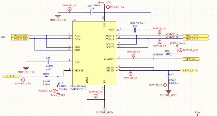
Attached schematic screen-capture :

Motor VDD = Battery voltage = 7.4v nominal

Input PWM directly from MCU

Output PWM directly to motor

R101 isn't assembled

  • Hi Eli,

    Is there a specific concern about how the motor would be damaged?

    Yes there may be cases based on the schematic shown. Depending on the resistance of the motor and the Vtrip voltage, there could be as much as 6A during startup or stall. What is the motor rating?

    The DRV8833 regulates current in the motor based on the value of Isense. When used in parallel mode as shown, you can achieve up to 4A assuming thermals are met, and possibly higher if the Isense is set above 4A.
  • See inserted questin:

    Is there a specific concern about how the motor would be damaged?
    Yes, I'm afraid that sometimes & somehow the driver enters to undefined state & drives current to the motor
    Yes there may be cases based on the schematic shown. Depending on the resistance of the motor and the Vtrip voltage, there could be as much as 6A during startup or stall. What is the motor rating?
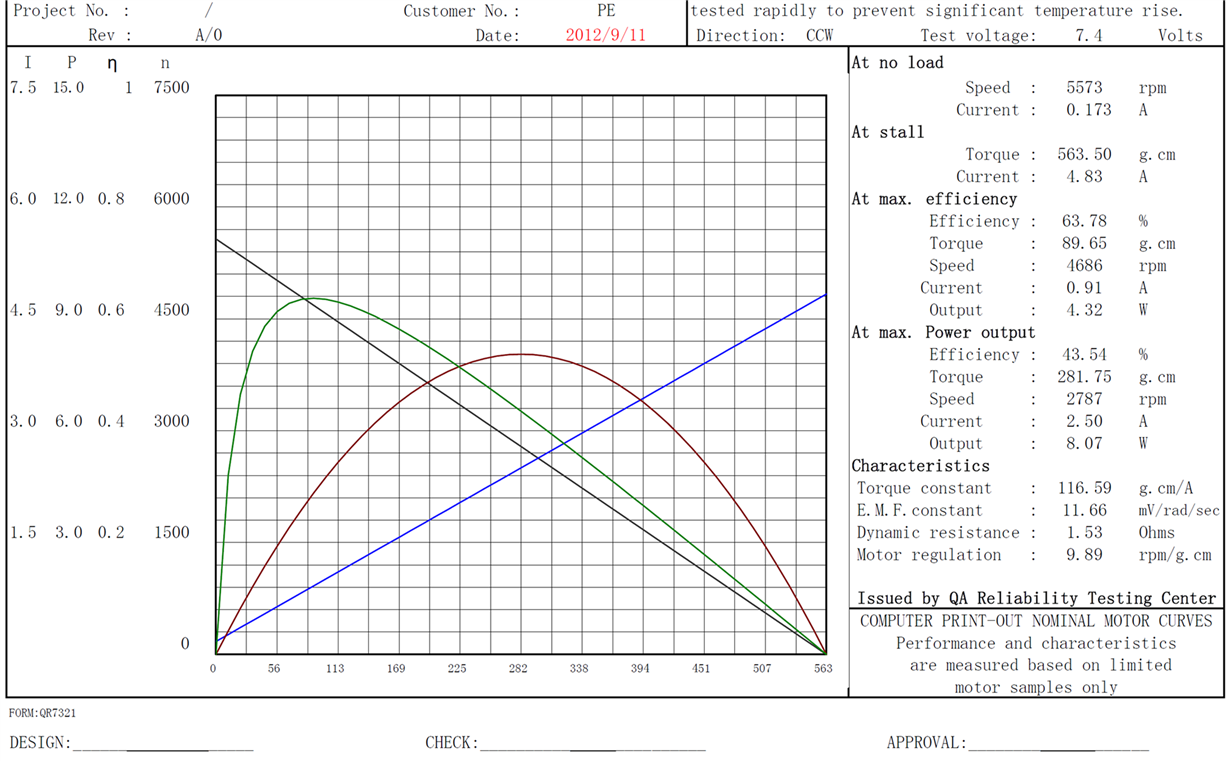
    Which case ? can you please be more specific ? it is very important, try to think if & how it can happen. attached motor's datasheet
    The DRV8833 regulates current in the motor based on the value of Isense. When used in parallel mode as shown, you can achieve up to 4A assuming thermals are met, and possibly higher if the Isense is set above 4A.

    As you can see we set the overcurrent protection to 5A, the motor isn't able to pull this current


  • Hi Eli,

    eli said:
    Is there a specific concern about how the motor would be damaged?
    Yes, I'm afraid that sometimes & somehow the driver enters to undefined state & drives current to the motor
    Yes there may be cases based on the schematic shown. Depending on the resistance of the motor and the Vtrip voltage, there could be as much as 6A during startup or stall. What is the motor rating?
    Which case ? can you please be more specific ? it is very important, try to think if & how it can happen. attached motor's datasheet

    Thank you for the motor specs. The case when the motor stalls, and becomes a resistor. In some cases the voltage is higher than the motor manufacturers rated current and can cause the motor to overheat. This does not appear to be the case for this motor.

    When the motor stalls, the current will be limited to approximately 4A. At some point this will cause a thermal shutdown and the nFAULT pin will assert. Monitoring the nFAULT pin provides feedback of potential problems like the overtemp or overcurrent.

    With regards to the device self waking, we have not heard of any issue like this.

  • Hi Rick 

    Is there any SW recommendation for operating the DRV8833 with MCU (PWM, Freq, Delays etc') ?

  • Hi Eli,

    There are really no recommendations, but there are some guidelines to consider.

    In many cases, the inputs are set to a static value, allow the motor to run at full speed. If this is desired, external PWM control is not required. The startup and stall current will be limited by the chopping current circuit.

    If using external PWM to control the speed,
    a) consider setting the PWM frequency above 20kHz to avoid the audible range. Lowering the PWM frequency into the audible range may help with switching losses but may create undesired noise.
    b) consider using slow decay to minimize the current ripple

    One delay to consider is the twake time. Allow 1ms for the device to wake up prior to driving the motor.
  • I have noticed that revision c of datasheet is released

    Why In this revision the feature "1.5A RMS, 2A peak" defined only for RTY package, while previous datasheet version it was defined in PWP & RTY packages ?

    Can you please advise for advantages and\or disadvantages between the two packages RTY & PWP (price, electrical & thermal conditions & ratings)

  • Hi

    Please advise for above question

  • Hi Eli

    The thermal performance of RTY is very similar or a little better than PWP package. 3A RMS/ 4A Peak should be fine for both the RTY and PWP package. RTY just saves your PCB room. For high current application, the PowerPAD of RTY package is also or more needed to have very good connection to large copper for the dissipation.

    Best regards,