


Hi,
I'm working with the kit DRV8301-hc-c2 with a BLDC motor.
I would like to implement the switching scheme in Figure

When I apply this pattern, see state 0 (AH in pwm, BL in ON) ; you can see figure below ,
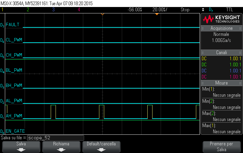
the device DRV8301 is always in fault.
Can I apply this switching scheme on the kit DRV8301 hc c2 without any fault ?
I attach these files :
- BLDC_int.c , see the level 1 , to find "pwm1.CmtnPointer = 0;" . then , I'm testing the state 0
- f2803xbldcpwm_BLDC.h , in BLDCPWM_MACRO(v) see only v.CmtnPointer = 0.
/* ==============================================================================
System Name:  	BLDC_Int

File Name:	  	BLDC_Int.c

Description:	Primary system file for the Real Implementation of Sensored
          		Trapeziodal Control of Brushless DC Motors (BLDC)

Originator:		D3 Engineering (www.d3engineering.com)
				Digital control systems Group - Texas Instruments

Note: In this software, the default inverter is supposed to be DRV8301/2-EVM.
=====================================================================================
 History:
-------------------------------------------------------------------------------------
 06-08-2011	Version 1.0:  F2803x target
===================================================================================*/

// Include header files used in the main function

#include "PeripheralHeaderIncludes.h"
#include "BLDC_Int-Settings.h"
#include "IQmathLib.h"
#include "BLDC_Int.h"
#include <math.h>

#ifdef DRV8301
union DRV8301_STATUS_REG_1 DRV8301_stat_reg1;
union DRV8301_STATUS_REG_2 DRV8301_stat_reg2;
union DRV8301_CONTROL_REG_1 DRV8301_cntrl_reg1;
union DRV8301_CONTROL_REG_2 DRV8301_cntrl_reg2;
Uint16 read_drv_status = 0;
#endif

#ifdef FLASH
#pragma CODE_SECTION(MainISR,"ramfuncs");
void MemCopy();
void InitFlash();
#endif

// Prototype statements for functions found within this file.
interrupt void MainISR(void);
void DeviceInit();

// State Machine function prototypes
//------------------------------------
// Alpha states
void A0(void);	//state A0
void B0(void);	//state B0
void C0(void);	//state C0

// A branch states
void A1(void);	//state A1
void A2(void);	//state A2
void A3(void);	//state A3

// B branch states
void B1(void);	//state B1
void B2(void);	//state B2
void B3(void);	//state B3

// C branch states
void C1(void);	//state C1
void C2(void);	//state C2
void C3(void);	//state C3

// Variable declarations
void (*Alpha_State_Ptr)(void);	// Base States pointer
void (*A_Task_Ptr)(void);		// State pointer A branch
void (*B_Task_Ptr)(void);		// State pointer B branch
void (*C_Task_Ptr)(void);		// State pointer C branch

// Used for running BackGround in flash, and ISR in RAM
extern Uint16 *RamfuncsLoadStart, *RamfuncsLoadEnd, *RamfuncsRunStart;

int16	VTimer0[4];			// Virtual Timers slaved off CPU Timer 0 (A events)
int16	VTimer1[4]; 		// Virtual Timers slaved off CPU Timer 1 (B events)
int16	VTimer2[4]; 		// Virtual Timers slaved off CPU Timer 2 (C events)
int16	SerialCommsTimer;

// Global variables used in this system

float32 T = 0.001/ISR_FREQUENCY;    // Samping period (sec), see parameter.h

Uint32 IsrTicker = 0;
Uint16 BackTicker = 0;

Uint16 PreviousState;

Uint32 VirtualTimer = 0;
Uint16 SpeedLoopFlag = FALSE;
Uint16 ILoopFlag = FALSE;
//_iq  DfuncTesting = _IQ(0.3);
//_iq  DfuncTesting = _IQ(0.1);
int16  DfuncTesting = (int16)_IQtoQ15(_IQ(0.1));//metto zero  0.5 � 50%
_iq IDCfdb;
//_iq  DfuncTesting = _IQ(0.1);
//_iq  DfuncStartup = _IQ(0.128);
//bici
//_iq  DfuncStartup = _IQ(0.105);//a 10Khz
_iq  DfuncStartup = _IQ(0.12);//a 20Khz
_iq CurrentStartup = _IQ(0.1);
_iq DcBusVolt = _IQ(0.0); //aggiunta bus voltage
_iq DcBusVoltage ;

Uint32 CmtnPeriodTarget = RAMP_END_RATE;
Uint32 CmtnPeriodSetpt = RAMP_START_RATE;
//Uint32 RampDelay = 1; //nema17
Uint32 RampDelay = 10;

_iq SpeedRef=_IQ(0.03);
#if defined(DRV8312)
_iq IRef = _IQ(0.1);
#endif
#if defined(DRV8301) || defined(DRV8302)
_iq IRef = _IQ(0.00);
_iq IRef_rc = _IQ(0.08);
#endif

int16 PwmDacCh1 = 0;
int16 PwmDacCh2 = 0;
int16 PwmDacCh3 = 0;
#if defined(DRV8301) || defined(DRV8302)
int16 PwmDacCh4 = 0;
#endif

int16 DlogCh1 = 0;
int16 DlogCh2 = 0;
int16 DlogCh3 = 0;
int16 DlogCh4 = 0;

//#if (BUILDLEVEL==LEVEL1)
//Uint16 DRV_RESET = 1;
//#else
Uint16 DRV_RESET = 0;
//#endif

volatile Uint16 EnableFlag = FALSE;
Uint16 RunMotor = FALSE;
//vecchi
//_iq BemfA_offset = _IQ(0.0065);	//modify offset after calibration step
//_iq BemfB_offset = _IQ(0.0069);	//modify offset after calibration step
//_iq BemfC_offset = _IQ(0.0060);	//modify offset after calibration step
//_iq IDC_offset = _IQ(0.5017);	//modify offset after calibration step
//bici
_iq BemfA_offset = _IQ(0.006484031677);//0.006560742855
_iq BemfB_offset = _IQ(0.006939411163);	//modify offset after calibration step 0.0.006721198559
_iq BemfC_offset = _IQ(0.005781710148);	//modify offset after calibration step 0.005826175213
_iq IDC_offset = _IQ(0.506891191);	//modify offset after calibration step 0.506904304

_iq cal_filt_gain;

// Instance PID regulator to regulate the DC-bus current and speed
PID_GRANDO_CONTROLLER pid1_idc = {PID_TERM_DEFAULTS,PID_PARAM_DEFAULTS,PID_DATA_DEFAULTS};
PID_GRANDO_CONTROLLER pid1_spd = {PID_TERM_DEFAULTS,PID_PARAM_DEFAULTS,PID_DATA_DEFAULTS};

// Instance a PWM driver instance
//PWM_CNTL pwmcntl1 = PWM_CNTL_DEFAULTS;
PWMGEN pwm1 = PWMGEN_DEFAULTS;

// Instance a PWM DAC driver instance
PWMDAC pwmdac1 = PWMDAC_DEFAULTS;

// Instance a ramp controller to smoothly ramp the frequency
RMPCNTL rc1 = RMPCNTL_DEFAULTS;

// Instance a RAMP3 Module
RMP3 rmp3 = RMP3_DEFAULTS;

// Instance a MOD6 Module
MOD6CNTDIR mod_dir1 = MOD6CNTDIR_DEFAULTS;

// Instance a IMPULSE Module
IMPULSE impl1 = IMPULSE_DEFAULTS;

//Instance an InstaSPIN_BLDC Module
INSTASPIN_BLDC InstaSPIN_BLDC1 = INSTASPIN_BLDC_DEFAULTS;

// Instance a SPEED_PR Module
SPEED_MEAS_CAP speed1 = SPEED_MEAS_CAP_DEFAULTS;

// Create an instance of DATALOG Module
DLOG_4CH dlog = DLOG_4CH_DEFAULTS;

// Instance a Hall effect driver
HALL3 hall1 = HALL3_DEFAULTS;

Uint16 hallCommutateFlag = 0;

Uint16 HallState = 0;

//int16 HallOffset = 0;
int16 HallOffset = 0;

Uint16 SpeedLoopPrescaler = 10;
Uint16 SpeedLoopCount = 0;

_iq spd_pid_kp;
_iq spd_pid_ki;
_iq spd_pid_kd;

_iq cur_pid_kp;
_iq cur_pid_ki;
_iq cur_pid_kd;

void main(void)
{

	DeviceInit();	// Device Life support & GPIO

// Only used if running from FLASH
// Note that the variable FLASH is defined by the compiler

#ifdef FLASH
// Copy time critical code and Flash setup code to RAM
// The  RamfuncsLoadStart, RamfuncsLoadEnd, and RamfuncsRunStart
// symbols are created by the linker. Refer to the linker files.
	MemCopy(&RamfuncsLoadStart, &RamfuncsLoadEnd, &RamfuncsRunStart);

// Call Flash Initialization to setup flash waitstates
// This function must reside in RAM
	InitFlash();	// Call the flash wrapper init function
#endif //(FLASH)


// Timing sync for background loops - originali
// Timer period definitions found in device specific PeripheralHeaderIncludes.h
//	CpuTimer1Regs.PRD.all =  mSec1;		// A tasks mSec1
//	CpuTimer2Regs.PRD.all =  mSec5;		// B tasks


// Tasks State-machine init
	Alpha_State_Ptr = &A0;
	A_Task_Ptr = &A1;
	B_Task_Ptr = &B1;

   // Waiting for enable flag set
   while (EnableFlag==FALSE)
    {
      BackTicker++;
    }

// Initialize all the Device Peripherals:
// This function is found in DSP280x_CpuTimers.c
   InitCpuTimers();
// Configure CPU-Timer 0 to interrupt every ISR Period:
// 60MHz CPU Freq, ISR Period (in uSeconds)
// This function is found in DSP280x_CpuTimers.c
   ConfigCpuTimer(&CpuTimer0, SYSTEM_FREQUENCY, 1000/ISR_FREQUENCY);
   StartCpuTimer0();

   //aggiunta timer1 and 2
   // Configure CPU-Timer 1,2 for background loops
      ConfigCpuTimer(&CpuTimer1, 60, 15000);
      ConfigCpuTimer(&CpuTimer2, 60, 50000);
      StartCpuTimer1();
      StartCpuTimer2();

#ifdef DRV8301
// Initialize SPI for communication to the DRV8301
	DRV8301_SPI_Init(&SpibRegs);
#endif

// Reassign ISRs.
// Reassign the PIE vector for TINT0 to point to a different
// ISR then the shell routine found in DSP280x_DefaultIsr.c.
// This is done if the user does not want to use the shell ISR routine
// but instead wants to use their own ISR.

	EALLOW;	// This is needed to write to EALLOW protected registers
	//PieVectTable.ADCINT1 = &MainISR;
	PieVectTable.TINT0 = &MainISR;
	EDIS;   // This is needed to disable write to EALLOW protected registers

// Enable PIE group 1 interrupt 7 for ADCINT1
    //PieCtrlRegs.PIEIER1.all = M_INT1;
	PieCtrlRegs.PIEIER1.all = M_INT7;
// Enable CPU INT1 for ADCINT1:
	IER |= M_INT1;
	// Enable Global realtime interrupt DBGM

// Initialize the PWM control module
	//pwmcntl1.PWMprd = SYSTEM_FREQUENCY*1000000*T/2;;				// Set the pwm period for this example
	//pwmcntl1.PWMprd = 0; //ponti aperti ?
	//PWM_CNTL_INIT_MACRO(pwmcntl1);
    //PWM_CNTL_MACRO(pwmcntl1);
	// Initialize PWM module
	    pwm1.PeriodMax = (SYSTEM_FREQUENCY/PWM_FREQUENCY)*1000;  // Asymmetric PWM
	    pwm1.DutyFunc = ALIGN_DUTY;            					 // DutyFunc = Q15
		BLDCPWM_INIT_MACRO(pwm1)

// Initialize PWMDAC module
	pwmdac1.PeriodMax = 500;   // 3000->10kHz, 1500->20kHz, 1000-> 30kHz, 500->60kHz
    pwmdac1.PwmDacInPointer0 = &PwmDacCh1;
    pwmdac1.PwmDacInPointer1 = &PwmDacCh2;
    pwmdac1.PwmDacInPointer2 = &PwmDacCh3;
#if defined(DRV8301) || defined(DRV8302)
    pwmdac1.PwmDacInPointer3 = &PwmDacCh4;
#endif
	PWMDAC_INIT_MACRO(pwmdac1)

// Initialize Hall module
// The hall order is not set in the first revolution, like was done on the DRV8312-kit code.
// Part of bringing up the motor is finding the correct hall order and modifying the hall1.HallMap[]
    hall1.DebounceAmount = 1;
    hall1.Revolutions = -1;
    hall1.HallMap[0] = 0;
    hall1.HallMap[1] = 4;
    hall1.HallMap[2] = 5;
    hall1.HallMap[3] = 2;
    hall1.HallMap[4] = 1;
    hall1.HallMap[5] = 3;
	HALL3_INIT_MACRO(hall1);
//  This is used to offset the hall order
	//HallOffset = 2; //nema17
    HallOffset = 3;//bici su rullo - bici a vuoto 4

// Initialize DATALOG module
    dlog.iptr1 = &DlogCh1;
    dlog.iptr2 = &DlogCh2;
    dlog.iptr3 = &DlogCh3;
    dlog.iptr4 = &DlogCh4;
    dlog.trig_value = 0x0;//0x1 default
    dlog.size = 0x0C8;   //200 campioni  0x0C8
#if (BUILDLEVEL < 5)
    dlog.prescalar = 25;
#else
    dlog.prescalar = 1;
#endif
    dlog.init(&dlog);

// Initialize ADC module (F2803XIDC_VEMF.H)
	ADC_MACRO_INIT()

 // Initialize the SPEED_PR module
 	speed1.InputSelect = 0;
 	speed1.BaseRpm = 120*(BASE_FREQ/POLES);			// Base RPM = 4999
 	speed1.SpeedScaler = (Uint32)(ISR_FREQUENCY/(6*BASE_FREQ*0.001));   // divider of 10

// Initialize RMPCNTL module
    rc1.RampDelayMax = 1;//2
    rc1.RampLowLimit = _IQ(-0.5);//-1.0 erano questi
    rc1.RampHighLimit = _IQ(0.5);//+1.0

// Initialize RMP3 module
	rmp3.DesiredInput = CmtnPeriodTarget;
	rmp3.Ramp3Delay = RampDelay;
    rmp3.Out = CmtnPeriodSetpt;
    rmp3.Ramp3Min = CmtnPeriodTarget;

//Initialize the INSTASPIN_BLDC module
// not used in code
	InstaSPIN_BLDC1.VaOffset = BemfA_offset;	//modify offset after calibration step
	InstaSPIN_BLDC1.VbOffset = BemfB_offset;	//modify offset after calibration step
	InstaSPIN_BLDC1.VcOffset = BemfC_offset;	//modify offset after calibration step
	InstaSPIN_BLDC1.Int_Threshold = _IQ(1.0);

// Initialize the PID_GRANDO_CONTROLLER module for dc-bus current
/*
	cur_pid_kp = _IQ(0.25);
	cur_pid_ki = _IQ(550.0);
	cur_pid_kd = _IQ(0.0);
    pid1_idc.param.Kp = cur_pid_kp;
    pid1_idc.param.Kr = _IQ(1.0);
	pid1_idc.param.Ki = _IQmpy(_IQ(T),cur_pid_ki);
	pid1_idc.param.Kd = _IQdiv(cur_pid_kd,_IQ(T));
    pid1_idc.param.Km = _IQ(1.0);
    pid1_idc.param.Umax = _IQ(0.95);
    pid1_idc.param.Umin = _IQ(-0.95);
*/

//dati bldc sensorless
	//nota : i controllori Kp e ki della texas instruments funziona carico
    //bisogna fare delle prove a carico
	//dati di default controllore
//	pid1_idc.param.Kp =    _IQ(2*(T/0.001));
//    pid1_idc.param.Ki =    _IQ(T/0.001);
	pid1_idc.param.Kp = _IQ(((2*PI)/(T*20))*LS*(BASE_CURRENT/BASE_VOLTAGE)); //dalla teoria di texas tuning pi 2*pi*0.25
	pid1_idc.param.Ki = _IQ(((T*RS)/LS));  //dalla teoria di texas tuning pi
//	pid1_idc.param.Kp = _IQ(((2*PI)/(T*20))*LS);
//	pid1_idc.param.Ki = _IQ(T/0.0005);
//	pid1_idc.param.Kp = _IQ(0.05);
	pid1_idc.param.Kd = _IQ(0/T);
	pid1_idc.param.Kr = _IQ(1.0);//1
    pid1_idc.param.Km = _IQ(1.0);
    pid1_idc.param.Umax = _IQ(0.95);//0.95
    pid1_idc.param.Umin = _IQ(-0.95);//-0.95


    // Initialize the PID_GRANDO_CONTROLLER module for dc-bus current
 /*       pid1_idc.param.Kp = _IQ(3.176*BASE_CURRENT/BASE_VOLTAGE);
        pid1_idc.param.Kr = _IQ(1.0);
    	pid1_idc.param.Ki = _IQ(T/0.0005);
    	pid1_idc.param.Kd = _IQ(0/T);
        pid1_idc.param.Km = _IQ(1.0);
        pid1_idc.param.Umax = _IQ(0.95);
        pid1_idc.param.Umin = _IQ(0.0);*/


// Initialize the PID_GRANDO_CONTROLLER module for Speed

	//spd_pid_kp = _IQ(0.50); //default
    spd_pid_kp = _IQ(0.05);
    spd_pid_ki = _IQ(10.0); //default
    //spd_pid_kp = _IQ(0.12089);
    //spd_pid_ki = _IQ(0.75);
    spd_pid_kd = _IQ(0.0);
    pid1_spd.param.Kp = spd_pid_kp;
    pid1_spd.param.Kr = _IQ(1.0);
	pid1_spd.param.Ki = _IQmpy( _IQ(T * SpeedLoopPrescaler) , spd_pid_ki);
	pid1_spd.param.Kd = _IQdiv(spd_pid_kd,_IQ(T*SpeedLoopPrescaler));
    pid1_spd.param.Km = _IQ(1.0);
    pid1_spd.param.Umax = _IQ(0.28);  // limite sul duty
    pid1_spd.param.Umin = _IQ(-0.28);

    //pid1_spd.param.Kp = _IQ(0.2*BASE_FREQ/BASE_CURRENT/(POLES/2));	//Anaheim
    //pid1_spd.param.Ki = _IQ(T*SpeedLoopPrescaler/0.3);				//Anaheim

// Initialize the current offset calibration filter
	cal_filt_gain = _IQ(T/(T+TC_CAL));

// Enable global Interrupts and higher priority real-time debug events:
	EINT;   // Enable Global interrupt INTM
	ERTM;	// Enable Global realtime interrupt DBGM


// IDLE loop. Just sit and loop forever:
	for(;;)  //infinite loop
	{
		BackTicker++;

		// State machine entry & exit point
		//===========================================================
		(*Alpha_State_Ptr)();	// jump to an Alpha state (A0,B0,...)
		//===========================================================

#ifdef DRV8301
		//read the status registers from the DRV8301
		if(read_drv_status)
		{
			DRV8301_stat_reg1.all = DRV8301_SPI_Read(&SpibRegs,STAT_REG_1_ADDR);
			DRV8301_stat_reg2.all = DRV8301_SPI_Read(&SpibRegs,STAT_REG_2_ADDR);
			read_drv_status = 0;
		}
#endif
	}
} //END MAIN CODE


//=================================================================================
//	STATE-MACHINE SEQUENCING AND SYNCRONIZATION FOR SLOW BACKGROUND TASKS
//=================================================================================

//--------------------------------- FRAMEWORK -------------------------------------
void A0(void)
{
	// loop rate synchronizer for A-tasks
//	if(CpuTimer0Regs.TCR.bit.TIF == 1)  //orig
	if(CpuTimer1Regs.TCR.bit.TIF == 1)
	{
//		CpuTimer0Regs.TCR.bit.TIF = 1;	// clear flag-orig
		CpuTimer1Regs.TCR.bit.TIF = 1;	// clear flag
		//-----------------------------------------------------------
		(*A_Task_Ptr)();		// jump to an A Task (A1,A2,A3,...)
		//-----------------------------------------------------------

		VTimer0[0]++;			// virtual timer 0, instance 0 (spare)
		SerialCommsTimer++;
	}

	Alpha_State_Ptr = &B0;		// Comment out to allow only A tasks
}

void B0(void)
{
	// loop rate synchronizer for B-tasks
	//if(CpuTimer1Regs.TCR.bit.TIF == 1)// orig
	if(CpuTimer2Regs.TCR.bit.TIF == 1)
	{
		//CpuTimer1Regs.TCR.bit.TIF = 1;				// clear flag orig
		CpuTimer2Regs.TCR.bit.TIF = 1;				// clear flag
		//-----------------------------------------------------------
		(*B_Task_Ptr)();		// jump to a B Task (B1,B2,B3,...)
		//-----------------------------------------------------------
		VTimer1[0]++;			// virtual timer 1, instance 0 (spare)
	}

	Alpha_State_Ptr = &A0;		// Allow C state tasks
}

//=================================================================================
//	A - TASKS (executed in every 1 msec)
//=================================================================================
//--------------------------------------------------------
void A1(void) // SPARE (not used)
//--------------------------------------------------------
{
	/*
	pid1_spd.param.Kp = spd_pid_kp;
	pid1_spd.param.Ki = _IQmpy( _IQ(T * SpeedLoopPrescaler) , spd_pid_ki);
	pid1_spd.param.Kd = _IQdiv(spd_pid_kd,_IQ(T*SpeedLoopPrescaler));
    */
	//capire se commentare


	//pid1_idc.param.Kp = _IQ(((2*PI)/(T*20))*LS*(BASE_CURRENT/BASE_VOLTAGE)); //dalla teoria di texas tuning pi 2*pi*0.25
	/*
	pid1_idc.param.Kp = _IQ(0.125*(BASE_CURRENT/BASE_VOLTAGE));
	pid1_idc.param.Ki = _IQ((T*RS)/LS);  //dalla teoria di texas tuning pi
	pid1_idc.param.Kd = _IQ(0/T);
    */
	if (EnableFlag == FALSE)
	{
#if defined (DRV8312)
		PHASE_A_OFF;
		PHASE_B_OFF;
		PHASE_C_OFF;
#endif
#if defined(DRV8301) || defined(DRV8302)
		//de-assert the DRV830x EN_GATE pin
		GpioDataRegs.GPBCLEAR.bit.GPIO39 = 1;
#endif

		RunMotor = FALSE;

		EALLOW;
	 	EPwm1Regs.TZFRC.bit.OST=1;
		//GpioDataRegs.GPACLEAR.bit.GPIO1 = 1;
		EPwm2Regs.TZFRC.bit.OST=1;
		//GpioDataRegs.GPACLEAR.bit.GPIO3 = 1;
		EPwm3Regs.TZFRC.bit.OST=1;
	    //GpioDataRegs.GPACLEAR.bit.GPIO5 = 1;
		EDIS;
	}
	else if((EnableFlag == TRUE) && (RunMotor == FALSE))
	{
#ifdef DRV8302
#if DRV_GAIN == 10
		GpioDataRegs.GPACLEAR.bit.GPIO25 = 1;	// GAIN = 10
#elif DRV_GAIN == 40
		GpioDataRegs.GPASET.bit.GPIO25 = 1;		// GAIN = 40
#else
#error  Invalid GAIN setting for DRV8302!!
#endif
		//GpioDataRegs.GPACLEAR.bit.GPIO24 = 1;	// M_OC - cycle by cycle current limit
		GpioDataRegs.GPASET.bit.GPIO24 = 1;		// M_OC - fault on OC
#endif
		//if we want the power stage active we need to enable the DRV830x
		//and configure it.
		if(DRV_RESET == 0)
		{
#if defined(DRV8301) || defined(DRV8302)
			//assert the DRV830x EN_GATE pin
			GpioDataRegs.GPBSET.bit.GPIO39 = 1;

			DELAY_US(50000);		//delay to allow DRV830x supplies to ramp up

#ifdef DRV8301
			DRV8301_cntrl_reg1.bit.GATE_CURRENT = 0;		// full current 1.7A
//			DRV8301_cntrl_reg1.bit.GATE_CURRENT = 1;		// med current 0.7A
//			DRV8301_cntrl_reg1.bit.GATE_CURRENT = 2;		// min current 0.25A
			DRV8301_cntrl_reg1.bit.GATE_RESET = 0;			// Normal Mode
			DRV8301_cntrl_reg1.bit.PWM_MODE = 0;			// six independant PWMs
//			DRV8301_cntrl_reg1.bit.OC_MODE = 0;				// current limiting when OC detected
			DRV8301_cntrl_reg1.bit.OC_MODE = 1;				// latched OC shutdown
//			DRV8301_cntrl_reg1.bit.OC_MODE = 2;				// Report on OCTWn pin and SPI reg only, no shut-down
//			DRV8301_cntrl_reg1.bit.OC_MODE = 3;				// OC protection disabled
//			DRV8301_cntrl_reg1.bit.OC_ADJ_SET = 0;			// OC @ Vds=0.060V
//			DRV8301_cntrl_reg1.bit.OC_ADJ_SET = 4;			// OC @ Vds=0.097V
//			DRV8301_cntrl_reg1.bit.OC_ADJ_SET = 6;			// OC @ Vds=0.123V
//			DRV8301_cntrl_reg1.bit.OC_ADJ_SET = 9;			// OC @ Vds=0.175V
			DRV8301_cntrl_reg1.bit.OC_ADJ_SET = 15;			// OC @ Vds=0.358V default
//			DRV8301_cntrl_reg1.bit.OC_ADJ_SET = 16;			// OC @ Vds=0.403V
//			DRV8301_cntrl_reg1.bit.OC_ADJ_SET = 17;			// OC @ Vds=0.454V
//			DRV8301_cntrl_reg1.bit.OC_ADJ_SET = 18;			// OC @ Vds=0.511V
			DRV8301_cntrl_reg1.bit.Reserved = 0;

//			DRV8301_cntrl_reg2.bit.OCTW_SET = 0;			// report OT and OC
			DRV8301_cntrl_reg2.bit.OCTW_SET = 1;			// report OT only
#if DRV_GAIN == 10
			DRV8301_cntrl_reg2.bit.GAIN = 0;				// CS amplifier gain = 10
#elif DRV_GAIN == 20
			DRV8301_cntrl_reg2.bit.GAIN = 1;				// CS amplifier gain = 20
#elif DRV_GAIN == 40
			DRV8301_cntrl_reg2.bit.GAIN = 2;				// CS amplifier gain = 40
#elif DRV_GAIN == 80
			DRV8301_cntrl_reg2.bit.GAIN = 3;				// CS amplifier gain = 80
#endif
			DRV8301_cntrl_reg2.bit.DC_CAL_CH1 = 0;			// not in CS calibrate mode
			DRV8301_cntrl_reg2.bit.DC_CAL_CH2 = 0;			// not in CS calibrate mode
			DRV8301_cntrl_reg2.bit.OC_TOFF = 0;				// normal mode
			DRV8301_cntrl_reg2.bit.Reserved = 0;

			//write to DRV8301 control register 1, returns status register 1
			DRV8301_stat_reg1.all = DRV8301_SPI_Write(&SpibRegs,CNTRL_REG_1_ADDR,DRV8301_cntrl_reg1.all);
			//write to DRV8301 control register 2, returns status register 1
			DRV8301_stat_reg1.all = DRV8301_SPI_Write(&SpibRegs,CNTRL_REG_2_ADDR,DRV8301_cntrl_reg2.all);
#endif
#endif
		}


		speed1.InputSelect = 0;
		speed1.NewTimeStamp = 0;
		speed1.OldTimeStamp = 0;
		speed1.EventPeriod = 0;
		speed1.Speed = 0;
		VirtualTimer = 0;

		rc1.EqualFlag = 0;
		rc1.RampDelayCount = 0;
		rc1.TargetValue = 0;
		rc1.SetpointValue = 0;   //aggiunta
		if(DfuncTesting >= _IQ(0.0))  //era >
		{
			mod_dir1.CntDirection = _IQ(1.0);
		}
		else
		{
			mod_dir1.CntDirection = _IQ(-1.0);
		}
		//rc1.SetpointValue = _IQmpy(DfuncStartup,mod_dir1.CntDirection);//tolta

		rmp3.DesiredInput = CmtnPeriodTarget;
    	rmp3.Out = CmtnPeriodSetpt;
		rmp3.Ramp3DelayCount = 0;
		rmp3.Ramp3DoneFlag = 0;

		impl1.Counter = 0;
		impl1.Out = 0;

		mod_dir1.Counter = 0;
		mod_dir1.TrigInput = 0;

		//ILoopFlag = FALSE;// se lo commento con enable false posso riprendere il controllo di copia
		SpeedLoopFlag = FALSE;

		pid1_idc.data.d1 = 0;
		pid1_idc.data.d2 = 0;
		pid1_idc.data.i1 = 0;
		pid1_idc.data.ud = 0;
		pid1_idc.data.ui = 0;
		pid1_idc.data.up = 0;
		pid1_idc.data.v1 = 0;
		pid1_idc.data.w1 = 0;
		pid1_idc.term.Out = 0;

		pid1_spd.data.d1 = 0;
		pid1_spd.data.d2 = 0;
		pid1_spd.data.i1 = 0;
		pid1_spd.data.ud = 0;
		pid1_spd.data.ui = 0;
		pid1_spd.data.up = 0;
		pid1_spd.data.v1 = 0;
		pid1_spd.data.w1 = 0;
		pid1_spd.term.Out = 0;

		RunMotor = TRUE;

		EALLOW;
			EPwm1Regs.TZCLR.bit.OST=1;
		    //GpioDataRegs.GPASET.bit.GPIO1 = 1;
		    //GpioDataRegs.GPASET.bit.GPIO3 = 1;
		    //GpioDataRegs.GPASET.bit.GPIO5 = 1;
		    EPwm2Regs.TZCLR.bit.OST=1;
			EPwm3Regs.TZCLR.bit.OST=1;
		EDIS;
	}

	//-------------------
	//the next time CpuTimer0 'counter' reaches Period value go to A2
	A_Task_Ptr = &A2;
	//-------------------
}

//-----------------------------------------------------------------
void A2(void) // SPARE (not used)
//-----------------------------------------------------------------
{

	//-------------------
	//the next time CpuTimer0 'counter' reaches Period value go to A3
	//GpioDataRegs.GPBTOGGLE.bit.GPIO34 = 1;//toggle led rosso su scheda ctr
	A_Task_Ptr = &A3;
	//-------------------
}

//-----------------------------------------
void A3(void) // SPARE (not used)
//-----------------------------------------
{

	//-----------------
	//the next time CpuTimer0 'counter' reaches Period value go to A1
	A_Task_Ptr = &A1;
	//-----------------
}


//=================================================================================
//	B - TASKS (executed in every 5 msec)
//=================================================================================

//----------------------------------- USER ----------------------------------------

//----------------------------------------
void B1(void) // Toggle GPIO-00
//----------------------------------------
{
	GpioDataRegs.GPBTOGGLE.bit.GPIO34 = 1;
	//-----------------
	//the next time CpuTimer1 'counter' reaches Period value go to B2
	B_Task_Ptr = &B2;
	//-----------------
}

//----------------------------------------
void B2(void) //  SPARE
//----------------------------------------
{

	//-----------------
	//the next time CpuTimer1 'counter' reaches Period value go to B3
	B_Task_Ptr = &B3;
	//-----------------
}

//----------------------------------------
void B3(void) //  SPARE
//----------------------------------------
{

	//-----------------
	//the next time CpuTimer1 'counter' reaches Period value go to B1
	B_Task_Ptr = &B1;
	//-----------------
}

// ==============================================================================
// =============================== MAIN ISR =====================================
// ==============================================================================


interrupt void MainISR(void)
{
// Verifying the ISR
    IsrTicker++;

	if(RunMotor)
	{
// =============================== LEVEL 1 ======================================
// Module check out (do not connect the motors)
// ==============================================================================

#if (BUILDLEVEL==LEVEL1)

	_iq iqVaIn;
	_iq iqVbIn;
	_iq iqVcIn;

// ------------------------------------------------------------------------------
//    ADC conversion and offset adjustment
// ------------------------------------------------------------------------------
	iqVaIn =  _IQ15toIQ((AdcResult.ADCRESULT1<<3));
	iqVbIn =  _IQ15toIQ((AdcResult.ADCRESULT2<<3));
	iqVcIn =  _IQ15toIQ((AdcResult.ADCRESULT3<<3));

	InstaSPIN_BLDC1.Vag = iqVaIn - InstaSPIN_BLDC1.VaOffset;		// Adjust for offset of Va_in
	InstaSPIN_BLDC1.Vbg = iqVbIn - InstaSPIN_BLDC1.VbOffset;		// Adjust for offset of Vb_in
	InstaSPIN_BLDC1.Vcg = iqVcIn - InstaSPIN_BLDC1.VcOffset;		// Adjust for offset of Vc_in

// ------------------------------------------------------------------------------
//    Connect inputs of the RMP3 module and call the RAMP Control 3 macro.
// ------------------------------------------------------------------------------
	rmp3.DesiredInput = CmtnPeriodTarget;
	rmp3.Ramp3Delay = RampDelay;
	RC3_MACRO(rmp3)

// ------------------------------------------------------------------------------
//    Connect inputs of the IMPULSE module and call the Impulse macro.
// ------------------------------------------------------------------------------
	impl1.Period = rmp3.Out;
	IMPULSE_MACRO(impl1)

// ------------------------------------------------------------------------------
//    Connect inputs of the MOD6 module and call the Mod 6 counter macro.
// ------------------------------------------------------------------------------
	mod_dir1.TrigInput = impl1.Out;
	MOD6CNTDIR_MACRO(mod_dir1)

// ------------------------------------------------------------------------------
//    Connect inputs of the PWM_DRV module and call the PWM signal generation
//	  update macro.
// ------------------------------------------------------------------------------
	//pwmcntl1.State = (int16)mod_dir1.Counter;
	//pwmcntl1.Duty = DfuncStartup;
	//PWM_CNTL_MACRO(pwmcntl1)
	//da qua
	// pwm1.CmtnPointer = (int16)mod_dir1.Counter;
	pwm1.CmtnPointer = 0;
	pwm1.DutyFunc = DfuncTesting;
    //pwm1.DutyFunc = 0;
	BLDCPWM_MACRO(pwm1)


// ------------------------------------------------------------------------------
//    Connect inputs of the PWMDAC module
// ------------------------------------------------------------------------------
	PwmDacCh1 = (int16)(mod_dir1.Counter * 4096.0L);
	PwmDacCh2 = _IQtoQ15(InstaSPIN_BLDC1.Vag);
	PwmDacCh3 = _IQtoQ15(InstaSPIN_BLDC1.Vbg);
#if defined(DRV8301) || defined(DRV8302)
	PwmDacCh4 = _IQtoQ15(InstaSPIN_BLDC1.Vcg);
#endif

// ------------------------------------------------------------------------------
//    Connect inputs of the DATALOG module
// ------------------------------------------------------------------------------
	DlogCh1 = (int16)mod_dir1.Counter;
	DlogCh2 = _IQtoQ15(InstaSPIN_BLDC1.Vag);
	DlogCh3 = _IQtoQ15(InstaSPIN_BLDC1.Vbg);
	DlogCh4 = _IQtoQ15(InstaSPIN_BLDC1.Vcg);

#endif // (BUILDLEVEL==LEVEL1)

// =============================== LEVEL 2 ======================================
// Verify ADC, run the motor open loop
// ==============================================================================

#if (BUILDLEVEL==LEVEL2)

	_iq iqVaIn;
	_iq iqVbIn;
	_iq iqVcIn;

// ------------------------------------------------------------------------------
//    ADC conversion and offset adjustment
//  BEMF is not used in sensored project, residual from sensorless project
// ------------------------------------------------------------------------------

	iqVaIn =  _IQ15toIQ((AdcResult.ADCRESULT1<<3));
	iqVbIn =  _IQ15toIQ((AdcResult.ADCRESULT2<<3));
	iqVcIn =  _IQ15toIQ((AdcResult.ADCRESULT3<<3));

	InstaSPIN_BLDC1.Vag = iqVaIn - InstaSPIN_BLDC1.VaOffset;		// Adjust for offset of Va_in
	InstaSPIN_BLDC1.Vbg = iqVbIn - InstaSPIN_BLDC1.VbOffset;		// Adjust for offset of Vb_in
	InstaSPIN_BLDC1.Vcg = iqVcIn - InstaSPIN_BLDC1.VcOffset;		// Adjust for offset of Vc_in

// ------------------------------------------------------------------------------
//    Connect inputs of the RMP3 module and call the Ramp control 3 macro.
// ------------------------------------------------------------------------------
	rmp3.DesiredInput = CmtnPeriodTarget;
	rmp3.Ramp3Delay = RampDelay;
	RC3_MACRO(rmp3)

// ------------------------------------------------------------------------------
//    Connect inputs of the IMPULSE module and call the Impulse macro.
// ------------------------------------------------------------------------------
	impl1.Period = rmp3.Out;
	IMPULSE_MACRO(impl1)

// ------------------------------------------------------------------------------
//    Connect inputs of the MOD6 module and call the Modulo 6 counter macro.
// ------------------------------------------------------------------------------
	if(DfuncStartup > _IQ(0.0))
	{
		mod_dir1.CntDirection = _IQ(1.0);
	}
	else
	{
		mod_dir1.CntDirection = _IQ(-1.0);
	}
	mod_dir1.TrigInput = impl1.Out;
	MOD6CNTDIR_MACRO(mod_dir1)

// ------------------------------------------------------------------------------
//    Connect inputs of the PWM_DRV module and call the PWM signal generation
//    update macro.
// ------------------------------------------------------------------------------
	pwmcntl1.State = (int16)mod_dir1.Counter;
	pwmcntl1.Duty = DfuncStartup;
	PWM_CNTL_MACRO(pwmcntl1)

// ------------------------------------------------------------------------------
//    Connect inputs of the PWMDAC module
// ------------------------------------------------------------------------------
	PwmDacCh1 = (int16)(mod_dir1.Counter * 4096.0L);
	PwmDacCh2 = _IQtoQ15(InstaSPIN_BLDC1.Vag);
	PwmDacCh3 = _IQtoQ15(InstaSPIN_BLDC1.Vbg);
#if defined(DRV8301) || defined(DRV8302)
	PwmDacCh4 = _IQtoQ15(InstaSPIN_BLDC1.Vcg);
#endif

// ------------------------------------------------------------------------------
//    Connect inputs of the DATALOG module
// ------------------------------------------------------------------------------
	DlogCh1 = (int16)mod_dir1.Counter;
	DlogCh2 = _IQtoQ15(InstaSPIN_BLDC1.Vag);
	DlogCh3 = _IQtoQ15(InstaSPIN_BLDC1.Vbg);
	DlogCh4 = _IQtoQ15(InstaSPIN_BLDC1.Vcg);

#endif // (BUILDLEVEL==LEVEL2)

// =============================== LEVEL 3 ======================================
// Auto-calibrate the current sensor and BEMF sense offsets
//  Only the current matters for the sensored project
// ==============================================================================

#if (BUILDLEVEL==LEVEL3)

	_iq IDCfdbk;
	_iq VsenseA;
	_iq VsenseB;
	_iq VsenseC;

// ------------------------------------------------------------------------------
//    ADC conversion and offset adjustment
// ------------------------------------------------------------------------------
	VsenseA =  _IQ15toIQ((AdcResult.ADCRESULT1<<3))-BemfA_offset;
	VsenseB =  _IQ15toIQ((AdcResult.ADCRESULT2<<3))-BemfB_offset;
	VsenseC =  _IQ15toIQ((AdcResult.ADCRESULT3<<3))-BemfC_offset;
    IDCfdbk=(_IQ15toIQ(AdcResult.ADCRESULT4<<3)-IDC_offset)<<1;
// ------------------------------------------------------------------------------
//  LPF to average the calibration offsets
//  Use the offsets calculated here to initialize BemfA_offset, BemfB_offset
//  and BemfC_offset so that they are used for the remaining build levels
// ------------------------------------------------------------------------------
    BemfA_offset = _IQmpy(cal_filt_gain,VsenseA) + BemfA_offset;
    BemfB_offset = _IQmpy(cal_filt_gain,VsenseB) + BemfB_offset;
    BemfC_offset = _IQmpy(cal_filt_gain,VsenseC) + BemfC_offset;
    IDC_offset = _IQmpy(cal_filt_gain,IDCfdbk) + IDC_offset;

// ------------------------------------------------------------------------------
//  force all PWMs to 0% duty cycle
// ------------------------------------------------------------------------------
	EPwm1Regs.CMPA.half.CMPA=0;	// PWM 1A - PhaseA
	EPwm2Regs.CMPA.half.CMPA=0;	// PWM 2A - PhaseB
	EPwm3Regs.CMPA.half.CMPA=0;	// PWM 3A - PhaseC

#endif // (BUILDLEVEL==LEVEL3)

// =============================== LEVEL 4 ======================================
// 	This build level will test the hall effect sensors.
// 		The order that the sensors is fired must me manually changed.  After the
//		"firing order" of the hall sensors is configured, pull hallCommutateFlag
// 		to commutate the motor using hall sensors.
// 	The speed module is also tested in the build level
// ==============================================================================

#if (BUILDLEVEL==LEVEL4)

	//aggiunta

		_iq iqVaIn;
		_iq iqVbIn;
		_iq iqVcIn;

	// ------------------------------------------------------------------------------
	//    ADC conversion and offset adjustment
	//  BEMF is not used in sensored project, residual from sensorless project
	// ------------------------------------------------------------------------------

		iqVaIn =  _IQ15toIQ((AdcResult.ADCRESULT1<<3));
		iqVbIn =  _IQ15toIQ((AdcResult.ADCRESULT2<<3));
		iqVcIn =  _IQ15toIQ((AdcResult.ADCRESULT3<<3));

		iqVaIn = iqVaIn - BemfA_offset ;		// Adjust for offset of Va_in
		iqVbIn = iqVbIn - BemfB_offset ;		// Adjust for offset of Vb_in
		iqVcIn = iqVcIn - BemfC_offset ;		// Adjust for offset of Vc_in

	_iq IDCfdbk;

// ------------------------------------------------------------------------------
//    ADC conversion and offset adjustment
// ------------------------------------------------------------------------------

#if defined(DRV8301) || defined(DRV8302)
    IDCfdbk=-((_IQ15toIQ(AdcResult.ADCRESULT4<<3)-IDC_offset)<<1);
#endif


// ------------------------------------------------------------------------------
//    Connect inputs of the RMP3 module and call the Ramp control 3 macro.
// ------------------------------------------------------------------------------
	rmp3.DesiredInput = CmtnPeriodTarget;
	rmp3.Ramp3Delay = RampDelay;
	RC3_MACRO(rmp3)

// ------------------------------------------------------------------------------
//    Connect inputs of the IMPULSE module and call the Impulse macro.
// ------------------------------------------------------------------------------
	impl1.Period = rmp3.Out;
	IMPULSE_MACRO(impl1)

// ------------------------------------------------------------------------------
//    Connect inputs of the HALL module and call the Hall sensor read macro.
// ------------------------------------------------------------------------------
	  HALL3_READ_MACRO(hall1)
	  HallState = (hall1.HallMap[hall1.HallGpioAccepted - 1] + HallOffset +6)%6;

// ------------------------------------------------------------------------------
//    Connect inputs of the SPEED_PR module and call the speed calculation macro.
// ------------------------------------------------------------------------------
  if (hall1.CmtnTrigHall==0x7FFF)
  {
       speed1.TimeStamp = VirtualTimer;
	   SPEED_PR_MACRO(speed1);
  }
  PreviousState = HallState;

// ------------------------------------------------------------------------------
//    Connect inputs of the MOD6 module and call the Modulo 6 counter macro.
// ------------------------------------------------------------------------------
	if(DfuncStartup > _IQ(0.0))
	{
		mod_dir1.CntDirection = _IQ(1.0);
	}
	else
	{
		mod_dir1.CntDirection = _IQ(-1.0);
	}
	mod_dir1.TrigInput = impl1.Out;
	MOD6CNTDIR_MACRO(mod_dir1)

// ------------------------------------------------------------------------------
//    Connect inputs of the PWM_DRV module and call the PWM signal generation
//    update macro.
// ------------------------------------------------------------------------------
if( hallCommutateFlag == TRUE){
	pwmcntl1.State = HallState;
}else{
	pwmcntl1.State = (int16)mod_dir1.Counter;
}
	pwmcntl1.Duty = DfuncStartup;
	PWM_CNTL_MACRO(pwmcntl1)

// ------------------------------------------------------------------------------
//    Connect inputs of the PWMDAC module
// ------------------------------------------------------------------------------
		PwmDacCh1 = _IQtoQ15(iqVaIn);//non va
		PwmDacCh2 = _IQtoQ15(iqVbIn);
		PwmDacCh3 = _IQtoQ15(iqVcIn);

// ------------------------------------------------------------------------------
//    Connect inputs of the DATALOG module
// ------------------------------------------------------------------------------
	DlogCh2 = (int16)mod_dir1.Counter;
//	DlogCh2 = (int16)HallState;
//	DlogCh3 = (int16)hall1.HallGpioAccepted;
//	DlogCh4 = (int16)1;

	DlogCh1 = _IQtoQ15(iqVaIn);
	DlogCh3 = _IQtoQ15(iqVbIn);
	DlogCh4 = _IQtoQ15(iqVcIn);

#endif // (BUILDLEVEL==LEVEL4)

// =============================== LEVEL 5 ======================================
//   Current loop is closed - NON FUNZIONA BENE
// ==============================================================================

#if (BUILDLEVEL==LEVEL5)


//--------originale
	_iq IDCfdbk;


 //   IDCfdb = (_IQ15toIQ(AdcResult.ADCRESULT4<<3)-IDC_offset)<<1;
    DcBusVolt = _IQ15toIQ((AdcResult.ADCRESULT5<<3));	     // DC Bus voltage meas.
    DcBusVoltage = BASE_VOLTAGE*DcBusVolt;
// ------------------------------------------------------------------------------
//    ADC conversion and offset adjustment
// ------------------------------------------------------------------------------

#if defined(DRV8301) || defined(DRV8302)
    IDCfdbk=-((_IQ15toIQ(AdcResult.ADCRESULT4<<3)-IDC_offset)<<1);//rimettere segno meno
#endif

// ------------------------------------------------------------------------------
//    Connect inputs of the RMP3 module and call the Ramp control 3 macro.
// ------------------------------------------------------------------------------
	rmp3.DesiredInput = CmtnPeriodTarget;
	rmp3.Ramp3Delay = RampDelay;
	RC3_MACRO(rmp3)

// ------------------------------------------------------------------------------
//    Connect inputs of the IMPULSE module and call the Impulse macro.
// ------------------------------------------------------------------------------
	impl1.Period = rmp3.Out;
	IMPULSE_MACRO(impl1)

// ------------------------------------------------------------------------------
//    Connect inputs of the HALL module and call the Hall sensor read macro.
// ------------------------------------------------------------------------------
	  HALL3_READ_MACRO(hall1)
	  HallState = (hall1.HallMap[hall1.HallGpioAccepted - 1] + HallOffset +6)%6;

// ------------------------------------------------------------------------------
//    Connect inputs of the SPEED_PR module and call the speed calculation macro.
// ------------------------------------------------------------------------------
  if (hall1.CmtnTrigHall==0x7FFF)
  {
       speed1.TimeStamp = VirtualTimer;
	   SPEED_PR_MACRO(speed1);
  }
  PreviousState = HallState;

// ------------------------------------------------------------------------------
//    Connect inputs of the MOD6 module and call the Modulo 6 counter macro.
// ------------------------------------------------------------------------------
	if(DfuncStartup > _IQ(0.0))
	{
		mod_dir1.CntDirection = _IQ(1.0);
	}
	else
	{
		mod_dir1.CntDirection = _IQ(-1.0);
	}
	mod_dir1.TrigInput = impl1.Out;
	MOD6CNTDIR_MACRO(mod_dir1)

// ------------------------------------------------------------------------------
//    Connect inputs of the PID_REG3 module and call the PID current controller
//	  macro.
// ------------------------------------------------------------------------------


	//varia il riferimento come una rampa

	if (ILoopFlag == TRUE)
	{
		//pid1_idc.data.ui = 0;
		//pid1_idc.data.i1 = 0;
		rc1.TargetValue = IRef_rc;
	    RC_MACRO(rc1);
	    pid1_idc.term.Ref = rc1.SetpointValue;
	}


	//pid1_idc.term.Ref = IRef;//serve per variazione istantanea cio� in assenza di una rampa
	pid1_idc.term.Fbk = _IQmpy(IDCfdbk,mod_dir1.CntDirection);
	PID_GR_MACRO(pid1_idc)

// ------------------------------------------------------------------------------
//    Connect inputs of the PWM_DRV module and call the PWM signal generation
//    update macro.
// ------------------------------------------------------------------------------
	//commutazione automatica
    if (rmp3.Ramp3DoneFlag == 0x7FFFFFFF)
    	hallCommutateFlag = TRUE;

	if( hallCommutateFlag == TRUE){
		pwmcntl1.State = HallState;
	}else{
		pwmcntl1.State = (int16)mod_dir1.Counter;
	}

	if (ILoopFlag == FALSE) {
		pwmcntl1.Duty = DfuncStartup;
		pid1_idc.data.ui = 0;
		pid1_idc.data.i1 = 0;
	}
//    else if (ILoopFlag == TRUE && IRef == 0 )
//    	pwmcntl1.Duty = 0;  //sicurezza
    else
    	pwmcntl1.Duty = pid1_idc.term.Out;  //ctr of current

	PWM_CNTL_MACRO(pwmcntl1)

// ------------------------------------------------------------------------------
//    Connect inputs of the DATALOG module
// ------------------------------------------------------------------------------
	DlogCh1 = _IQtoQ15(pwmcntl1.Duty);
	DlogCh2 = _IQtoQ15(IDCfdbk);
	DlogCh3 = _IQtoQ15(DcBusVoltage);
	DlogCh4 = (int16)HallState;
#endif // (BUILDLEVEL==LEVEL5)

// =============================== LEVEL 6 ======================================
//  This closes the a speed loop and outputs a duty cycle.  No current sense is
//  	used.
// ==============================================================================

#if (BUILDLEVEL==LEVEL6)

	_iq IDCfdbk;

// ------------------------------------------------------------------------------
//    ADC conversion and offset adjustment
//     Not used, reading is taken for debugging
// ------------------------------------------------------------------------------

#if defined(DRV8301) || defined(DRV8302)
    IDCfdbk=-((_IQ15toIQ(AdcResult.ADCRESULT4<<3)-IDC_offset)<<1);
#endif

// ------------------------------------------------------------------------------
//    Connect inputs of the RMP3 module and call the Ramp control 3 macro.
// ------------------------------------------------------------------------------
	rmp3.DesiredInput = CmtnPeriodTarget;
	rmp3.Ramp3Delay = RampDelay;
	RC3_MACRO(rmp3)

// ------------------------------------------------------------------------------
//    Connect inputs of the IMPULSE module and call the Impulse macro.
// ------------------------------------------------------------------------------
	impl1.Period = rmp3.Out;
	IMPULSE_MACRO(impl1)

// ------------------------------------------------------------------------------
//    Connect inputs of the HALL module and call the Hall sensor read macro.
// ------------------------------------------------------------------------------
	  HALL3_READ_MACRO(hall1)
	  HallState = (hall1.HallMap[hall1.HallGpioAccepted - 1] + HallOffset +6)%6;

// ------------------------------------------------------------------------------
//    Connect inputs of the SPEED_PR module and call the speed calculation macro.
// ------------------------------------------------------------------------------
  if (hall1.CmtnTrigHall==0x7FFF)
  {
       speed1.TimeStamp = VirtualTimer;
	   SPEED_PR_MACRO(speed1);
  }
  PreviousState = HallState;

// ------------------------------------------------------------------------------
//    Connect inputs of the MOD6 module and call the Modulo 6 counter macro.
// ------------------------------------------------------------------------------
	if(DfuncStartup > _IQ(0.0))
	{
		mod_dir1.CntDirection = _IQ(1.0);
	}
	else
	{
		mod_dir1.CntDirection = _IQ(-1.0);
	}
	mod_dir1.TrigInput = impl1.Out;
	MOD6CNTDIR_MACRO(mod_dir1)

// ------------------------------------------------------------------------------
//    Connect inputs of the PID_REG3 module and call the PID speed controller
//	  macro.
// ------------------------------------------------------------------------------
if ( hallCommutateFlag == TRUE && (SpeedLoopCount >= SpeedLoopPrescaler) ){
      pid1_spd.term.Ref = SpeedRef;
      pid1_spd.term.Fbk = speed1.Speed;
      PID_GR_MACRO(pid1_spd)
      SpeedLoopCount = 1;
}else {
	  SpeedLoopCount++;
}

if ( hallCommutateFlag == FALSE){
	  pid1_spd.data.ui = 0;
	  pid1_spd.data.i1 = 0;
	  SpeedLoopCount = 1;
}
// ------------------------------------------------------------------------------
//    Connect inputs of the PWM_DRV module and call the PWM signal generation
//    update macro.
// ------------------------------------------------------------------------------
if( hallCommutateFlag == TRUE )
{
	pwmcntl1.State = HallState;
	//pwmcntl1.Duty = pid1_spd.term.Out;
	//commento tutto perch� � la parte di un flag

	if ( SpeedLoopFlag == TRUE )
		pwmcntl1.Duty = pid1_spd.term.Out;   // controlled Speed duty-cycle
	else
	{
		pwmcntl1.Duty = DfuncStartup;
			pid1_spd.data.ui = 0;  // lasciare o no?
			pid1_spd.data.i1 = 0;  //
	}
}
else
{
	pwmcntl1.State = (int16)mod_dir1.Counter;
	pwmcntl1.Duty = DfuncStartup;
}

	PWM_CNTL_MACRO(pwmcntl1)

// ------------------------------------------------------------------------------
//    Connect inputs of the DATALOG module
// ------------------------------------------------------------------------------
	DlogCh1 = (int16)SpeedRef;
	DlogCh2 = (int16)speed1.Speed;
	DlogCh3 = (int16)mod_dir1.Counter;
	DlogCh4 = _IQtoQ15(IDCfdbk);
#endif // (BUILDLEVEL==LEVEL6)


// =============================== LEVEL 7 ======================================
// Verify the closed speed loop and speed PI controller
// ==============================================================================

#if (BUILDLEVEL==LEVEL7)


	_iq IDCfdbk;

// ------------------------------------------------------------------------------
//    ADC conversion and offset adjustment
//     Not used, reading is taken for debugging
// ------------------------------------------------------------------------------

#if defined(DRV8301) || defined(DRV8302)
    IDCfdbk=-((_IQ15toIQ(AdcResult.ADCRESULT4<<3)-IDC_offset)<<1);
#endif

// ------------------------------------------------------------------------------
//    Connect inputs of the RMP3 module and call the Ramp control 3 macro.
// ------------------------------------------------------------------------------
	rmp3.DesiredInput = CmtnPeriodTarget;
	rmp3.Ramp3Delay = RampDelay;
	RC3_MACRO(rmp3)

// ------------------------------------------------------------------------------
//    Connect inputs of the IMPULSE module and call the Impulse macro.
// ------------------------------------------------------------------------------
	impl1.Period = rmp3.Out;
	IMPULSE_MACRO(impl1)

// ------------------------------------------------------------------------------
//    Connect inputs of the HALL module and call the Hall sensor read macro.
// ------------------------------------------------------------------------------
	  HALL3_READ_MACRO(hall1);
	  HallState = (hall1.HallMap[hall1.HallGpioAccepted - 1] + HallOffset +6)%6;

// ------------------------------------------------------------------------------
//    Connect inputs of the SPEED_PR module and call the speed calculation macro.
// ------------------------------------------------------------------------------
  if (hall1.CmtnTrigHall==0x7FFF)
  {
       speed1.TimeStamp = VirtualTimer;
	   SPEED_PR_MACRO(speed1);
  }
  PreviousState = HallState;

// ------------------------------------------------------------------------------
//    Connect inputs of the MOD6 module and call the Modulo 6 counter macro.
// ------------------------------------------------------------------------------
	if(DfuncStartup > _IQ(0.0))
	{
		mod_dir1.CntDirection = _IQ(1.0);
	}
	else
	{
		mod_dir1.CntDirection = _IQ(-1.0);
	}
	mod_dir1.TrigInput = impl1.Out;
	MOD6CNTDIR_MACRO(mod_dir1)

// ------------------------------------------------------------------------------
//    Connect inputs of the PID_REG3 module and call the PID speed controller
//	  macro.
// ------------------------------------------------------------------------------
if ( hallCommutateFlag == TRUE && (SpeedLoopCount >= SpeedLoopPrescaler) ){
      pid1_spd.term.Ref = SpeedRef;
      pid1_spd.term.Fbk = speed1.Speed;
      PID_GR_MACRO(pid1_spd)
      SpeedLoopCount = 1;
}else {
	  SpeedLoopCount++;
}

if ( hallCommutateFlag == FALSE){
	  pid1_spd.data.ui = 0;
	  pid1_spd.data.i1 = 0;
	  SpeedLoopCount = 1;
}

// ------------------------------------------------------------------------------
//    Connect inputs of the PID_REG3 module and call the PID current controller
//	  macro.
// ------------------------------------------------------------------------------
	pid1_idc.term.Ref = pid1_spd.term.Out;
	pid1_idc.term.Fbk = IDCfdbk;
	PID_GR_MACRO(pid1_idc)

// ------------------------------------------------------------------------------
//    Connect inputs of the PWM_DRV module and call the PWM signal generation
//    update macro.
// ------------------------------------------------------------------------------
if( hallCommutateFlag == TRUE){
	pwmcntl1.State = HallState;
	pwmcntl1.Duty = pid1_idc.term.Out;
}else{
	pwmcntl1.State = (int16)mod_dir1.Counter;
	pwmcntl1.Duty = DfuncStartup;
}
	PWM_CNTL_MACRO(pwmcntl1)

// ------------------------------------------------------------------------------
//    Connect inputs of the DATALOG module
// ------------------------------------------------------------------------------
	DlogCh1 = (int16)mod_dir1.Counter;
	DlogCh2 = (int16)HallState;
	DlogCh3 = (int16)HallState;
	DlogCh4 = _IQtoQ15(IDCfdbk);

#endif // (BUILDLEVEL==LEVEL7)


// ------------------------------------------------------------------------------
//    Call the PWMDAC update macro.
// ------------------------------------------------------------------------------
	PWMDAC_MACRO(pwmdac1)

// ------------------------------------------------------------------------------
//    Call the DATALOG update function.
// ------------------------------------------------------------------------------
    dlog.update(&dlog);

// ------------------------------------------------------------------------------
//    Increase virtual timer and force 15 bit wrap around
// ------------------------------------------------------------------------------
	VirtualTimer++;
	VirtualTimer &= 0x00007FFF;

	}//end if(RunMotor)


#if (DSP2803x_DEVICE_H==1)
/* Enable more interrupts from this timer
	EPwm1Regs.ETCLR.bit.INT = 1;

// Acknowledge interrupt to recieve more interrupts from PIE group 3
	PieCtrlRegs.PIEACK.all = PIEACK_GROUP3;
*/

	AdcRegs.ADCINTFLGCLR.bit.ADCINT1 = 1;		// Clear ADCINT1 flag reinitialize for next SOC

// Acknowledge interrupt to recieve more interrupts from PIE group 1
	PieCtrlRegs.PIEACK.all = PIEACK_GROUP1;

#endif

#if (DSP280x_DEVICE_H==1)
// Enable more interrupts from this timer
	EPwm1Regs.ETCLR.bit.INT = 1;

// Acknowledge interrupt to recieve more interrupts from PIE group 3
	PieCtrlRegs.PIEACK.all = PIEACK_GROUP3;
#endif


}// ISR Ends Here


//===========================================================================
// No more.
//===========================================================================
thanks in advance


