This thread has been locked.

If you have a related question, please click the "Ask a related question" button in the top right corner. The newly created question will be automatically linked to this question.

can i use DRV8662 to drive high resistive load?

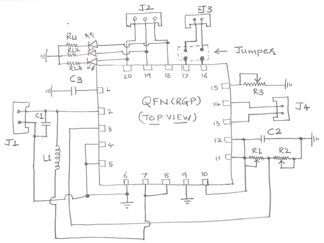
Hi i am designing high voltage amplifier to drive high value resistive load, i built the circuit based on the evaluation board of DRV 8662, here i have attached the circuit diagram of this IC, please check if this is wrong, i fabricated the PCB based on this circuit, now when i tried to test this board with capacitive load of 100nF, 400V, i do not get the expected output. i applied input of 200mVpp sine wave, gain set for 100, (G0=1, Vdd, G1=0 GND, EN=1, Vdd) Vdd=5V, R1= 392k, R2= 9.76k Rext= 7.5k, L=4.7uH, now, if C1 , C2(Boost capacitor)  and C3 (Pump capacitor) 100nF, but voltage rating are not matching to the specified in the Evaluation board, does it make any difference, if it makes then that may be the reason why i am not getting correct out put? anf if it works can i use the same circuit for DC voltage amplification?

  • Hello Chintan,

    Could you describe in more detail what you mean by the output isn't working? Also, you mentioned 400V, but this device can only go to +/-100V. Could you clarify?

    Finally, the capacitors should be rated for the voltage they intended to be exposed to.

  • Hi Rodney,

    thanks for your prompt reply. yes sure, out put is zero, i.e. flat on the Digital Oscilloscope. now to the 400V, i think if i want to drive any load through this circuit, i need to meet atleast a voltage rating of the output of this circuit, beyond should not be a problem. like we select capacitors for voltage regulator such that the voltage rating of the capacitor should be more than the expected DC output, with this logic i selected a capacitor as a load in this circuit having value of 100nF and voltage rating of 400V. 

    i hope i have answered you questions. 

    thanks with best regards

    Chintan

  • Hello Chintan,

    Thanks for the clarification, the 400V is the rating of the capacitor and not the expected output so you are correct. In regards to debug, can you give any more information of the signals (Vpump, EN, VDD and input current)?

    Also just to be sure, how are you measuring the output?

  • Hi Rodney,

    thanks, EN is connected to Vdd and in this case Vdd is +5V, input is 200mVpp sine wave. 

    i did not measure Vpump, what should be the voltage across it? i will try to measure today?

    thanks and regards

    Chintan

  • Hi Chintan,
    It should be greater than Vdd so around 8V or so.
  • Hi Rodney,

    i was unable to test the board, today i replaced the capacitors as per the specified in the datasheet. previously i was not been able to get voltage across Vpump, Vfb, and PVdd, VBST, today after replacing these capacitors with proper voltage rating, i am reading the following voltages across these variables as under

    Vpump= 7.8V DC

    Vfb= 1.34V DC

    PVdd= 55.2V DC

    VBst= 55.2V DC

    but still i am not reading output what can be the issue now. 

    EN pin is High

    Gain 1 is Low

    Gain 0 is High

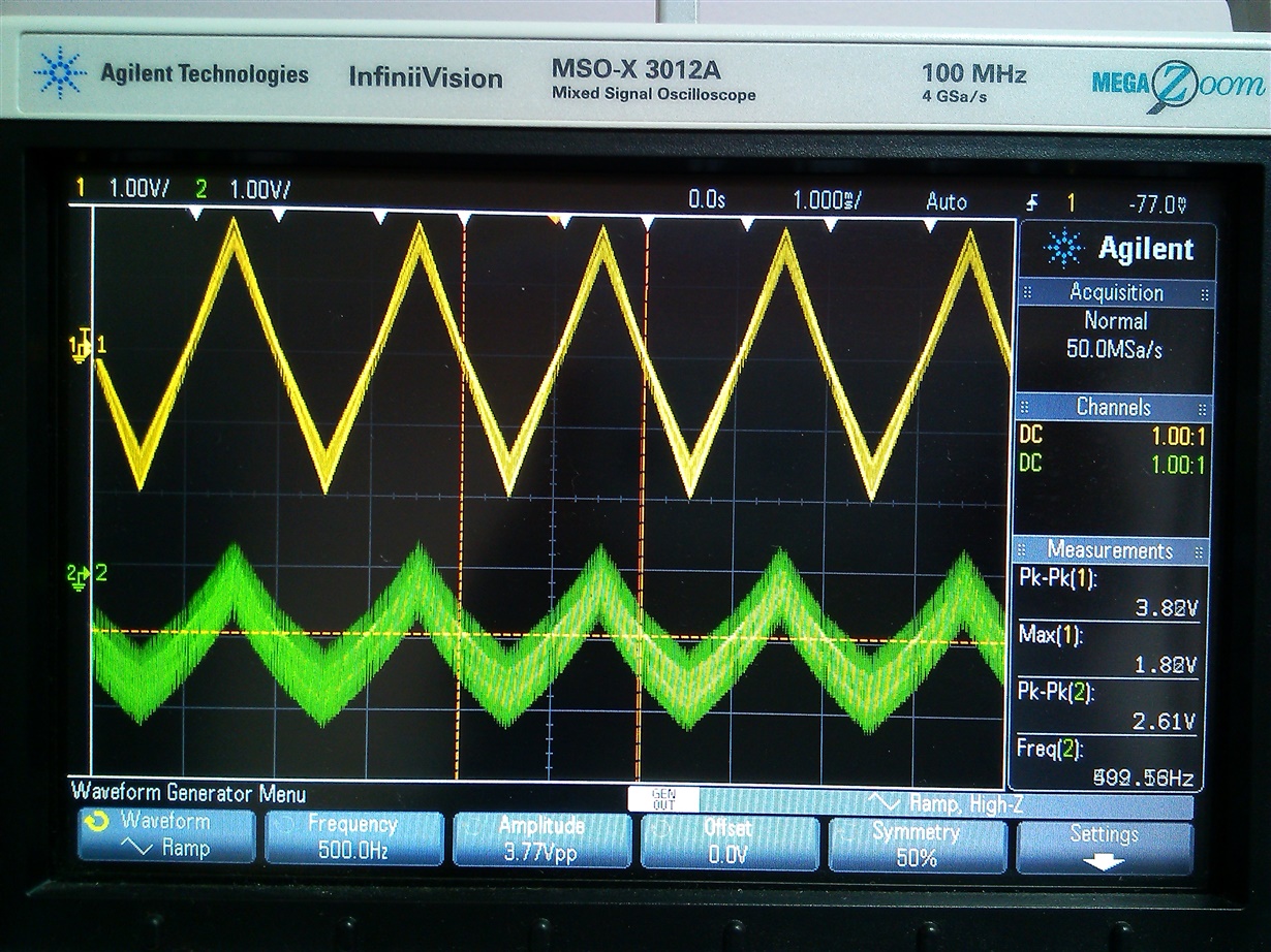
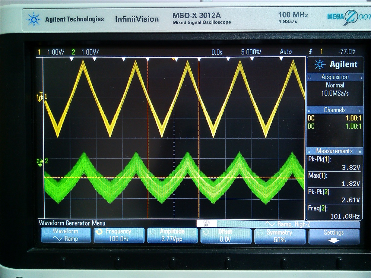
    Vin = single ended 400mV 100Hz triangular signal

    please guide to reach some conclusion. 

    with best regards

    Chintan

  • Chintan,

    Could you send a scope shot of your input signals and output signals?

  • Hi Rodney,

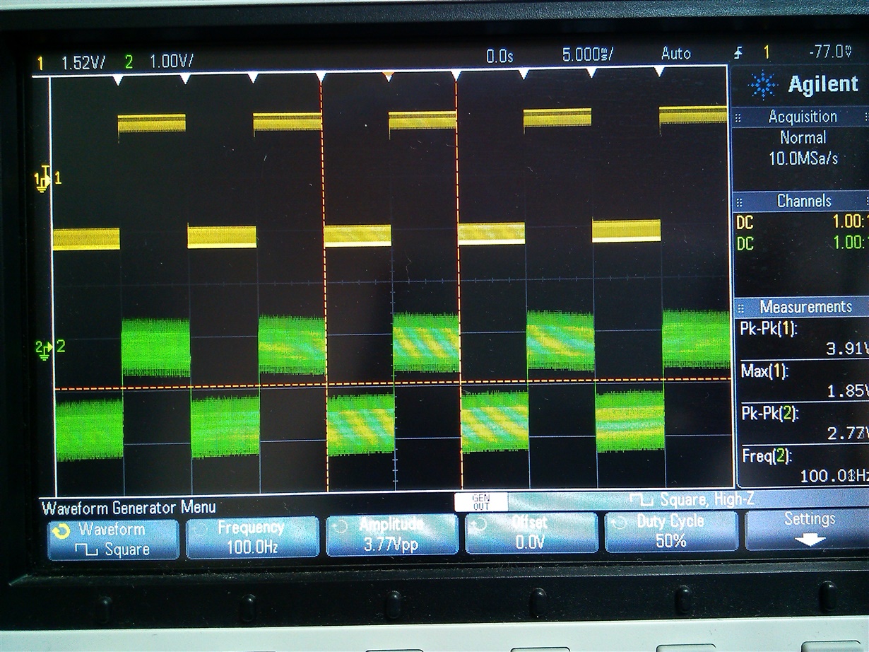
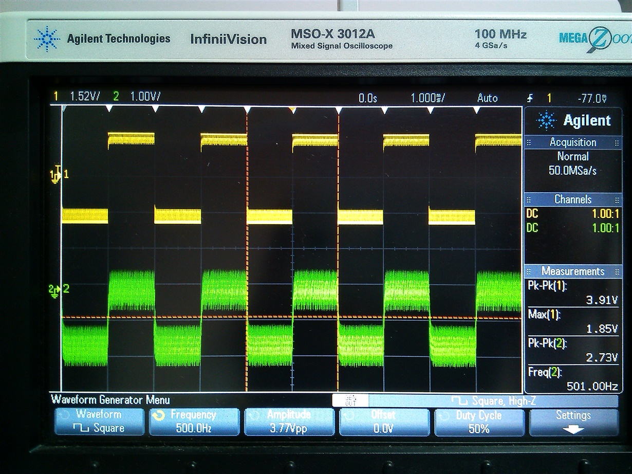
    here i have attached the screen shots of input and output waveform for two different types of signal for two different frequency.

    i also tried to check if changing gain resolves the issue but still output is same as for other gain setting, does it mean my amplifier section has some issue?

    because as per the gain setting boosting circuit works perfectly fine, please have a look at these screen shot and guide.

    with best regards

    Chintan

  • Chintan,

    You are correct, these signals do not look correct. How are you grounding your scope probes? In order to take these measurements, you need to connect a probe to OUT+ to GND and OUT- to GND and then do a math function to subtract the two. (This can also be done for the input side..)