This thread has been locked.

If you have a related question, please click the "Ask a related question" button in the top right corner. The newly created question will be automatically linked to this question.

DRV2605 External trigger problem

Other Parts Discussed in Thread: DRV2605

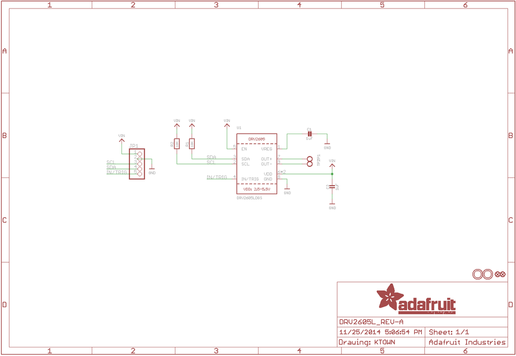
I'm using a DRV2605 on Adafruit's breakout (schematic attached) and am running into issues with the external trigger mode. I'm attempting to use external trigger to allow for continuous play of the stored haptic waveforms without needing to monitor the device status, by pulling the IN/TRIG pin to high and simply switching between internal and external trigger modes to get discrete/continuous waveform play. The device works normally when in internal trigger mode, but when switched to external level trigger, it will only function if the IN/TRIG pin is floating, and not when it is connected to any constant voltage, whether that is Vdd, ground, or an intermediate level. External edge trigger behaves identically. I am using a dime ERM using provided settings from Adafruit, at 4.7Vdd. 

I can't seem to find information about whether the IN/TRIG pin is pulled up or otherwise regulated while floating in the datasheet, and I'm very confused as to why 4.7V at the input pin is causing the motor to stop. Any suggestions?

  • I don't know what happens.

    I check the schematics, the EN pin is HIGH, so the EN pin shouldn't be a problem.

    I suppose the waveform sequencer has been properly set.

    if we change the mode to external level trigger mode (set 0x02 to register 0x01), a rising edge (1.3V above) of IN/Trig should trigger the waveform playback, while a falling edge will cancel it.

    can we check your Vdd noise? as you are connecting the Vdd to the In/Trig pin.

    Thanks.

  • Yes, the waveform sequencer is set in code earlier. I've taken a look at my VDD noise and it sawtooths a little bit (~.1V) around 4.7V since the power source I'm currently using has multiple settings. It never drops below the 1.3 digital logic point, but all the same, could that be causing the issue?

    I should note that in general, I'm getting very irregular behavior out of the drivers (even the ones on my own custom PCBs rather than Adafruits). In many cases, drivers cease to appear on the I2C bus, respond irregularly to commands, and otherwise do not behave as described on the data sheet. I'm wondering if I am operating under conditions that are causing them to fail regularly, though they never return error values when queried for Status. 

    Thanks for your help.

  • the DRV2605 in Adafruits board works regularly in internal-trigger mode, right?

    Does the DRV2605 on your own PCB work normally in internal-trigger mode? if not, we need to check the schematics difference between your board and the Adafruits.

    the IN/Trig pin is VDD tolerant. I think it's not the voltage level caused the iregulary behaviour in external-level trigger mode.

    can we use another trigger source rather than the VDD to trigger it, just for test purpose?

  • Lucian,

    Quick question- Are all the GNDs connected together? sounds like the references are not set properly. Whats the swing on the VDD sawtooth?

    thanks,

    Gautham

  • Ok, I've tried some more things but am still having issues. To start, it turns out the I2C irregularities were a different issue, which had to do with the capacitor on the REG pin. That's been solved, so it's just the external trigger that isn't working. I've also tried a new power source that does not have any significant voltage swing and the problem still persists. Behavior is still unpredictable; with the new setup, level trigger doesn't work at all, and edge trigger now works at startup when held to Vdd but ceases to function when any changes are made. 

    Can anyone explain how exactly the external triggers will affect the GO bit over multiple waveform cycles? Say I'm attempting to hold the GO bit high, by just tying the TRIG pin to Vdd. Then I initialize the system like this (Written as arduino code, but it's fairly self explanatory):

      drv.begin(); //move out of standby and create ERM settings
      drv.setMode(DRV2605_MODE_EXTTRIGLVL); //set mode to external level trigger
      drv.selectLibrary(1);
      
      // set the effect to play (simple click)
      drv.setWaveform(0, 1);       // play effect 
      drv.setWaveform(1, 0);       // end waveform


    What I'd hoped this would do would be to set the waveform to a click and hold the GO bit high using the level trigger so it would just play over and over again. This would be an admittedly hacky way to get the DRV to play a library waveform continuously without needing to monitor the driver to see when a waveform completes. When I wanted to get discrete waveforms, I could simply switch back to internal trigger. Obviously this isn't working quite as I'd hoped, so I'd like to know if this is handling the GO bit incorrectly or if there's a much better way of achieving the same goal. 

    EDIT: also, just to answer some of your questions: 

    • the board works fine in internal trigger mode
    • all the grounds are connected properly
    • my PCBs have the same errors as the adafruit ones

  • the external level trigger mode:

    the rising edge will trigger the waveform, and the falling edge will cancel the waveform.

    so if we keep the In/Trig HIGH, i don't think it will trigger the waveform again and again.