This thread has been locked.

If you have a related question, please click the "Ask a related question" button in the top right corner. The newly created question will be automatically linked to this question.

DRV8825 Rsense value vs. microstep current distortion

Other Parts Discussed in Thread: DRV8825, DRV8846, DRV8880, DRV8824

Hello,


I'm working on a design that uses three unipolar hybrid steppers, with three very different sizes/working current. For the sake of simplicity in the design, I'm using the DRV8825 for all of them - as it seems they're all within the operation range of the driver.

But I believe that besides the selection of Vref to set the chopper current, Rsense must be adjusted for each motor (the bigger supports 1.5A peak current running cold, the smaller only 100mA).

Now that I'm making some integration tests and adjusting the currents on the steppers I have some doubts that remain unsolved after searching trough the TI forum and some application notes:

1) What are the considerations to select the proper value for Rsense?

Though lower values can handle bigger currents, the datasheet only states that the sense pin should be in the range -0.8V to +0.8V. For a 1A peak output current, for example, it seems 0.22Ω is too high. And for a 0.1A, do I need a bigger value to ensure a good control on the current? Does the motor inductance accounts for the selection of Rsense?

2)  How the wire length from the driver output to the motor affects the system performance?

For the bigger Nema 17 one some issues occurred:

- The driver was heating at a 400mA peak current on the output - changing the Rsense value from 0.22Ω to 0.10Ω seemed to solve that issue

- It was configured to use 1/16 uStepping, but the motor was 'choking', what appeared in the current signal measured in one of the motor wires as a distorted sine wave (below)

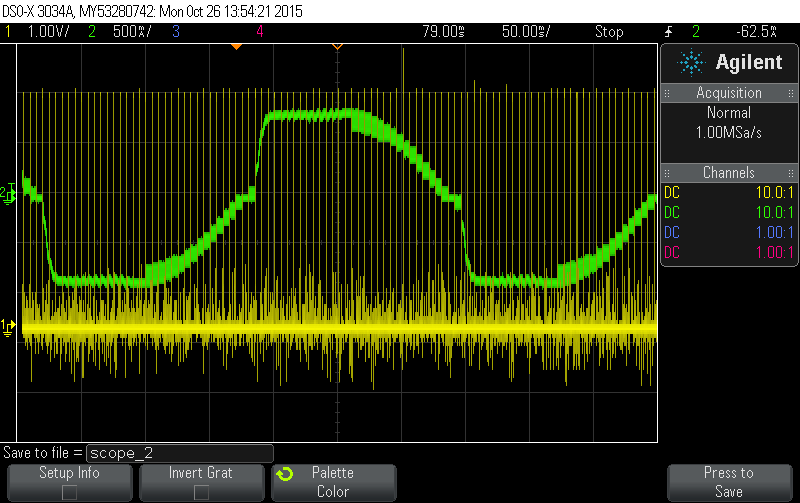
The yellow signal is the probe attached to the step pin of the driver, and the green is a current probe in one of the windings of the motor.

- putting the driver in fast decay mode instead of the default mixed decay (leaving the decay pin open) fixed that too:

Now I'm working on the intermediate motor, that should run at 400mA peak current. But if I raise the current by increasing the Vref, the sine wave gets distorted to a square:

So, my guess is that the inductance of the motor is too high (74mH), so I cannot increase the current without changing the Rsense value from the current 0.22Ω.

What determinates the chopper operation frequency, by the way?

  • Hi Gabriel,

    Gabriel Marques said:
    1) What are the considerations to select the proper value for Rsense?

    Generally, the resistor should be selected to create the maximum voltage at the comparator. For example, at 1A using a .5 Ohm resistor will allows the voltage at the comparator to vary from 0 to 2.5V. This provides more voltage between each step.

    Gabriel Marques said:
    2)  How the wire length from the driver output to the motor affects the system performance?

    The wire length adds inductance which can affect the performance. Additional inductance reduces the rate of current change in the motor, which reduces the maximum speed.

    Gabriel Marques said:
    What determinates the chopper operation frequency, by the way?

    The chopper operation is set by the internal oscillator. Once the current has reached the limit, the decay mode is entered until the next internal PWM cycle begins.

    The reason that you are seeing the square wave is the mixed decay is slow decay when the current is increasing. The current injected during the blanking time is more than the current removed during the slow decay. The current increases until an equilibrium is reached. Fast decay corrects this as you noted.

    New devices such as the DRV8846 and DRV8880 have been introduced to automatically select the decay mode, and minimize current ripple.

  • Thanks, the motors are running ok now. Just one consideration, the chopper switching is around 30KHz, which should be inaudible.
    But they sound like a loud white noise when not moving. Is there any thing I can try to dim the noise?
  • Hi Gabriel,

    Now that you are using fast decay, it is possible to create audible signals. This depends on where the chopping current hits in a PWM cycle. If you zoom into your current waveform you may see some periods that stretch into audible frequencies.

    There are a couple of options:
    1) When holding (not moving), lowering VREF to reduce the torque may help.
    2) Switching to the DRV8824 may help. It is a pin compatible version with 50kHz PWM frequency. The difference is the RDSon is higher, reducing the max current.
    3) Switching to our latest generation device, the DRV8880 with AutoTune. AutoTune is designed to minimize the current ripple. The device uses slow decay as much as possible, minimizing long fast decay times followed by drive times to re-insert the current removed.

  • Hi Gabriel,

    The prior post had a typo on the part number. It should have been the DRV8880 and has been corrected on the forum.