This thread has been locked.

If you have a related question, please click the "Ask a related question" button in the top right corner. The newly created question will be automatically linked to this question.

DRV8312 current waveform

Other Parts Discussed in Thread: DRV8312

Hi,

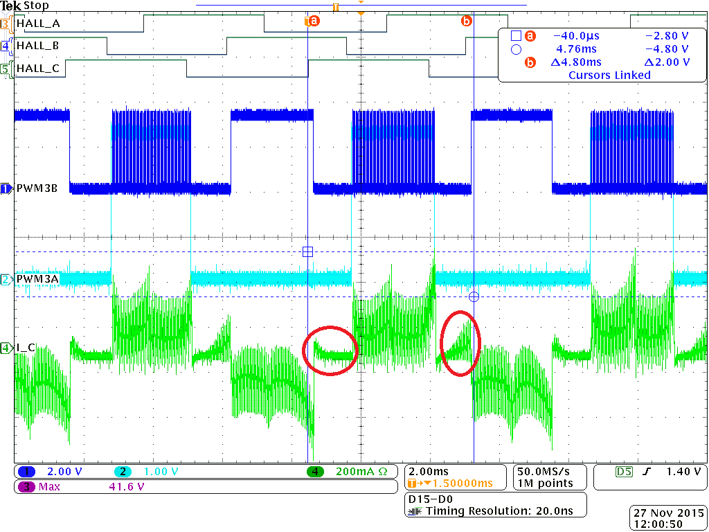
I have DRV8312-C2 kit. Using BLDC_GUI code, i get this current waveform for both the sensored and sensorless options.

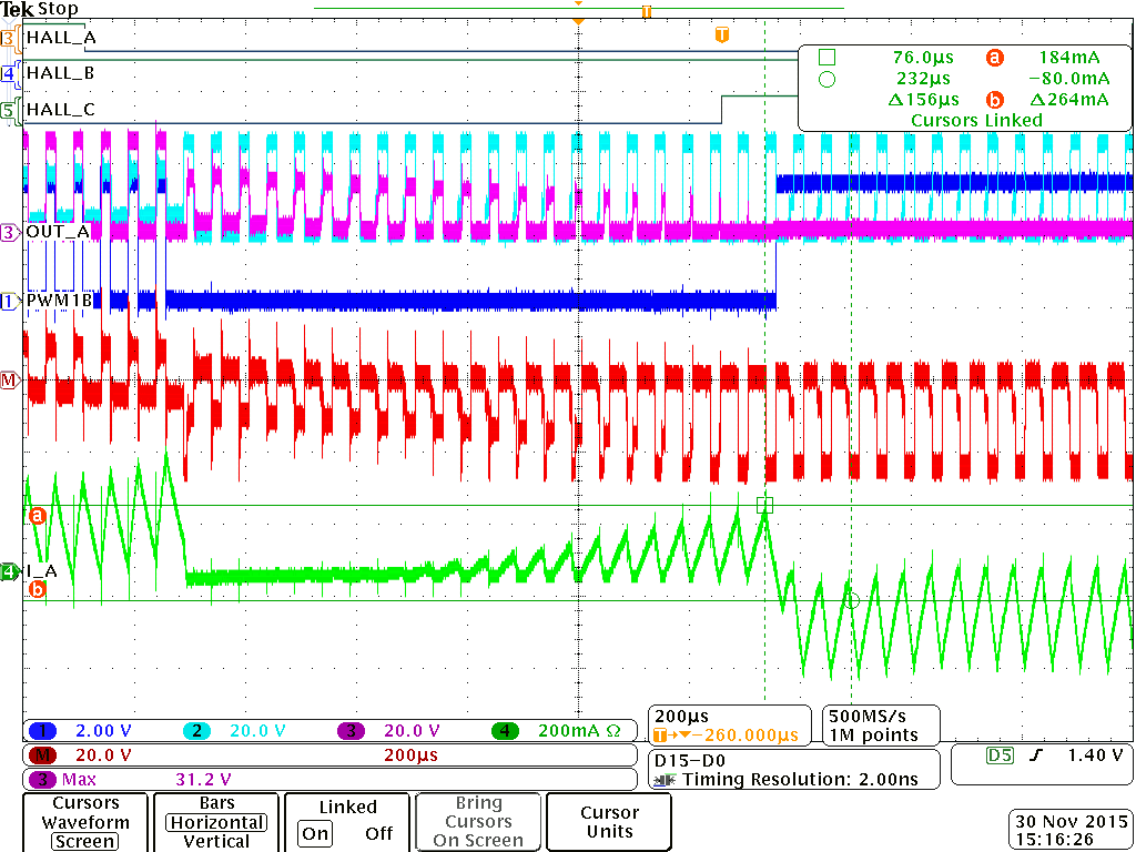
Any idea, why current still flows on the red circled areas? Technically, at those instances, the current should flow on the high and low side FET (i.e. high-impedance state). Hence, in those areas, it should just be a flat 0 A level. The green curve is the current measured on phase C of the motor that came with the kit.

Any ideas?

  • Could you also give the phase node voltage waveform? Is above sensored or sensorless?

    Best regards,
  • Hi Wilson,

    I see the same curve for both sensored or sensorless.

    The dark blue curve labeled PWM3B is actually the phase node voltage and PWM3A is PWM3 of the motor driver DRV8312.

  • It is possible that some of the recirculation current during PWM off may take the path of the third high Z phase body diodes. Could you check a state in 100% duty cycle running, to see whether there is still the current in HiZ phase?

    Best regards,
  • Can you guide me here? I am using the  DRV8312GUI_Main.c. What exactly needs to be modified?

    Thanks!

  • Do you mean how to get 100% duty cycle? Are still using the GUI or changing everything with your own code? Also please post your question on C2000 forum for code changing or optimizing requests. 

    Best regards,

  • I am running the code DRV8312GUI_Main.c in CCS and modifying the code as needed.
  • Hi Wilson,

    I did two methods to modify PWM to 100% Duty Cycle as you asked.

    Looking at the BLDCPWM_Macro(),

    Method 1: (changes made to the original code are in Red)

    if (v.CmtnPointer==0) /* */\

       { /* */\

         EPwm1Regs.AQCSFRC.bit.CSFB = 2;       /* Forcing continuous high on output B of EPWM1   */\

         /*EPwm1Regs.AQCTLB.bit.CAU = 2;     */    /* Set high when CTR = CMPA on UP-count */\

         /*EPwm1Regs.AQCTLB.bit.ZRO = 1;    */     /* Set low when CTR = Zero */\

         /*EPwm1Regs.CMPA.half.CMPA = (int16)(Tmp>>15);*/ /* PWM signal on output B of EPWM1 (Q15 -> Q0) */\

         EPwm1Regs.AQCSFRC.bit.CSFA = 2;       /* Forcing a continuous High on output A of EPWM1   */\

    /* */\

         EPwm2Regs.AQCSFRC.bit.CSFA = 1;       /* Forcing a continuous Low on output A of EPWM2   */\

         EPwm2Regs.AQCSFRC.bit.CSFB = 2;       /* Forcing a continuous High on output B of EPWM2   */\

    /* */\

         EPwm3Regs.AQCSFRC.bit.CSFA = 1;       /* Forcing a continuous Low on output A of EPWM3   */\

         EPwm3Regs.AQCSFRC.bit.CSFB = 1;       /* Forcing a continuous Low on output B of EPWM3   */\

       }

    Method 2: (changes made to the original code are in Red)

    if (v.CmtnPointer==0) /* */\
    { /* */\
    EPwm1Regs.AQCSFRC.bit.CSFB = 0; /* Forcing disabled on output B of EPWM1 */\
    EPwm1Regs.AQCTLB.bit.CAU = 2; /* Set high when CTR = CMPA on UP-count */\
    EPwm1Regs.AQCTLB.bit.ZRO = 2; /* Set high when CTR = Zero */\
    EPwm1Regs.CMPA.half.CMPA = (int16)(Tmp>>15); /* PWM signal on output B of EPWM1 (Q15 -> Q0) */\
    EPwm1Regs.AQCSFRC.bit.CSFA = 2; /* Forcing a continuous High on output A of EPWM1 */\
    /* */\
    EPwm2Regs.AQCSFRC.bit.CSFA = 1; /* Forcing a continuous Low on output A of EPWM2 */\
    EPwm2Regs.AQCSFRC.bit.CSFB = 2; /* Forcing a continuous High on output B of EPWM2 */\
    /* */\
    EPwm3Regs.AQCSFRC.bit.CSFA = 1; /* Forcing a continuous Low on output A of EPWM3 */\
    EPwm3Regs.AQCSFRC.bit.CSFB = 1; /* Forcing a continuous Low on output B of EPWM3 */\
    } /* */\


    Those changes were applied to all 6 CmtnPrd States.

    Using either of those 2 Methods, the motor would not spin at all. 


    Any thoughts?


    Thanks.


  • Sorry I made a miss statement on "100%" duty cycle.

    What is OC mode you are using? If you are using cycle by cycle current limit mode, all PWM_x inputs can't be 0% all 100% for DRV8312, As the OC state must be cleared by the edge of the inputs PWM. So you can use 99.9% or very narrow low pulse instead of 100%(constant High) and 0.1% or very narrow high pulse instead of 0%(constant Low).

    Also you can just ramp up your PWM duty to the 99.9% instead of directly goes to that high, it may cause OCP issues.

    Best regards,
  • The M1 switch on the board is set to High (i.e. Three-phase or three half bridges with OC latching shutdown (no cycle-by-cycle current limit)).

    Also, by changing the SpeedRef, the Duty Cycle can be changed. So i set the speed to maximum to see Duty Cycle close to 100%. The higher the Duty cycle, the higher current is seen on those 2 0-level commutation state.
  • So in this case, when you say the motor is not moving, is there a nFAULT report from DRV8312? What's you VM voltage and motor phase resistor? In latch mode, you need make sure the MAX/Stall current will be less than the latch threshold.

    Best regards,
  • there was no fault report seen when i used the InstaSPIN GUI. And hence, the motor run with PWM Duty cycle set to maximum allowed per Speed setting.

    Motor did not run when i applied Method 1 or Method 2 to the BLDCGUI_Main.c. How would i be able to see a FAULT report from DRV8312 when i run the code using CCS?

    Are you referring to resistors R38, R42 and R44 as motor phase resistors? If yes, I have never changed them. They are 95.3kohms according to the schematic diagram of the control board (DRV8312-C2Kit).

    Maybe it would help if you can duplicate my issue with your own board.
  • Please just probe the nFAULT pin and monitor the waveform. External pull up is needed for nFAULT pin.

    For the phase resistor, I mean the motor coil resistor between U V or V W or U W. Just test it simply with a multi-meter. Is start up or stall or ramping condition, the peak current can be VM/R_phase, if this value is higher than your latch setting level, cycle by cycle current limit is needed.

    For the current waveform, could you also test other two phases? also the waveform of adding some load to the motor.

    Best regards,
  • Here are the waveforms for the 2 other phases:

    By Vm you simply mean the phase voltage, right?

  • Switching M1 to low (cycle-by-cycle current limit) does not make any difference. Same current waveform seen.
  • Hi Wilson,

    Maybe I am missing something. But i just don't see the whole point of either CBC or latching shutdown would matter. The ODC_Adjust resistor on the board is 30kohm setting the max current threshold to 8.8A. 

    Question about ODC_Adjust resistor, what is the minimum current threshold that can be set? Table 2 states 200 kohm value for 1.4A.

    The motor coil resistance is measured to be about 1.8 ohms.

    The Math Function for the oscilloscope plot below is OUT_A - OUT_B. This value is 800mV (at the current overshoot of the supposed 0 Ampere level current).

    The current at this point is 184 mA (see plot below). 

    So 800mV / 1.8 ohm = 444.4 mA which is way above than the measured value of 184 mA.

    Hope you can shed light on this matter.

    Thanks!