Hello.
I want to drive a unipolar stepper motor of 5 wires with an impedance of 14ohm between the common wires and which one of the remaining wires.
Initially, I used the ULN2002N and i was successful and the following step was to drive the same motor with the DRV8805.
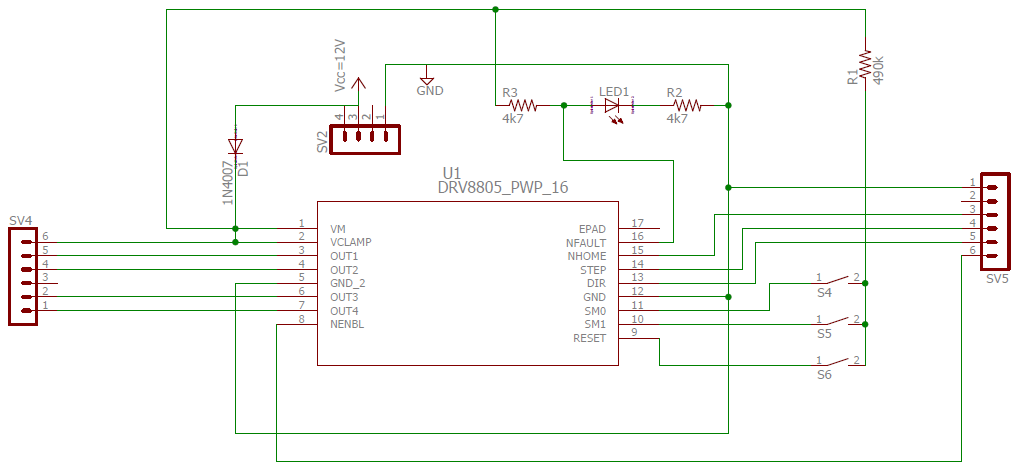
The schematic for the DRV8805 is the picture below.
The original design didn't have neither the resistor R1 nor R3.
Instead of resistor R1 there was a short-circuit.
A second design added resistor R3 and a third design added resistor R1 and remove R3 resistance.
The thermal pad was not connected to any other pin.
In the first two designs with DRV8805, the driver burned and a few ms/s of contact with the skin was enough to burn the finger.
In the first case, SM1 pull-down resistor gave place to a short-circuit (41ohm) and the Reset to an infinite resistance.
In the second case, SM1 pull-down resistor halved and the SM0 pull-down resistor gave place to an infinite resistance.
In the third design I was more carefull and added components step by step.
At the beginning, neither the motor was connected to SV4 nor the command device at SV5.
The power supply was connected to SV2 and S5 was closed. Everything worked nice. Current consumption of 10mA.
The following step was to connect the command device at the SV5 and 4 load resistors (4k7 each) to the diferent outputs with Vcc in the other resistor terminal.
At this point, it was possible to see the DRV8805 driving the load resistors. The idle current was the same.
The third step was to connect the motor. The DRV8805 made a sound (again) and i stopped immediatly.
The driver keeps working without the motor but the idle current double ( in the previous 2 drivers the current was, after damage, some hundreds of mA).
What i want to know is: What is necessary to do in my circuit to avoid this serious problem?
Thank you
.


