This thread has been locked.

If you have a related question, please click the "Ask a related question" button in the top right corner. The newly created question will be automatically linked to this question.

Issues with DRV8833

Other Parts Discussed in Thread: DRV8833

Hi,

I've got a DRV8833 in HTSSOP16 package that I put on a TSSOP16 breakout (without heatsink). This leads to the heatsink not being connected to ground. I assumed this wouldn't matter since it's just used for heat sink, is this correct? I'm trying to build www.ti.com/.../drv8833.pdf (page 12, 8.2 typical application) but it doesn't work and I've checked the connections on my breakout board 3x now. I've got Ain1 and Ain2 in VCC (6V) and gnd respectively but no output. It seems that fault is low and I'm not quite sure why. Also, do I need the (correct) caps or should it work without them? Thanks!

EDIT: On page 3 in datasheet it says "both GND pin and device PowerPAD pust be connected to ground". I'm assuming this answers my question?

  • Hi Kenny,

    At low currents, the DRV8833 should work without a connection to the thermal pad.

    The device requires C1 and C2 on 8.2 to operate. The device may operate at low currents without C4 although it is recommended.

    Is nSLEEP input a logic high? This will place the device in run mode.
    Do you have a pullup resistor on nFAULT?
  • Hi Rick,

    nSleep is logic high yes, I put the correct cap values and the motor turns now in one direction only. If I swap the input pins to VCC/GND nothing happens. I haven't found the reason for this yet. Also I didn't see any mention in datasheet that nFault needs to have an external pullup other than maybe in Figure 10. Thanks for the help!

    Kenny
  • Hi Kenny,

    Glad to hear you have made some progress. Can you remove the motor and set the inputs to GND/VCC (the non working condition)? The outputs should then be low/high following the logic table in Table 1. This will confirm the device is operating as expected.

    If the outputs are working as expected, reconnect the motor and probe the outputs when the inputs are GND/VCC. Are the outputs still low and high as expected, or are they toggling? Can you provide a scope capture of the outputs if toggling?

    Are you using a sense resistor to limit the current? What is the value?

    With regard to nFAULT, it is listed as an output drain output in the pin functions section. As an open drain, it requires a pull-up. The benefit is that several open drain outputs can be connected together with a single pullup. This can reduce the number of GPIOs required to identify a fault in the system.
  • Hello,

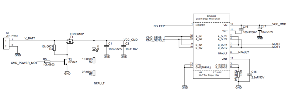
    It seems that I have quite the same problem with the same schematic as figure 7 of the datasheet :

    I try to start the motor, but the NFAULT occurs (LOW).

    I checked that, when I turn ON :

    A_IN1 is low

    A_IN2 is hight (3.3Vdc)

    NSLEEP is hight (3.3Vdc)

    VCC_CMD is hight (7.2Vdc) 

    I can see a small glitch on A_OUT1 and A_OUT2 and then the signals stay to GND. The NFAULT is pulled to the GND.

    I checked that, when I turn OFF :

    A_IN1 is low

    A_IN2 is low

    NSLEEP is hight (3.3Vdc)

    VCC_CMD is low

    If I turn ON and OFF and ON again quikly, the motor works, and the NFAULT is hight. But in a "normal mode", when I juste turn ON, the motor does not move.

    Do you have any idea of what is happening ?

  • Hi user4509385,

    You may be experiencing overcurrent events. The outputs may turn on for a few microseconds then off for ~1.4ms before repeating.

    Have you looked at the outputs on the scope?
  • Hello Rick,

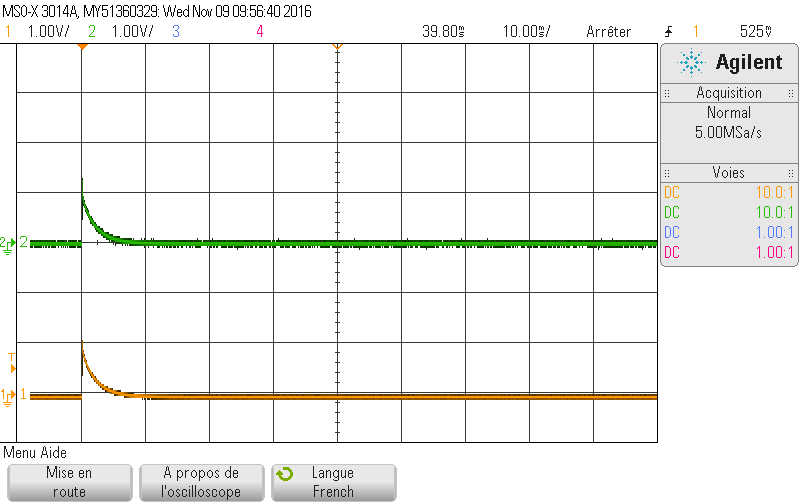
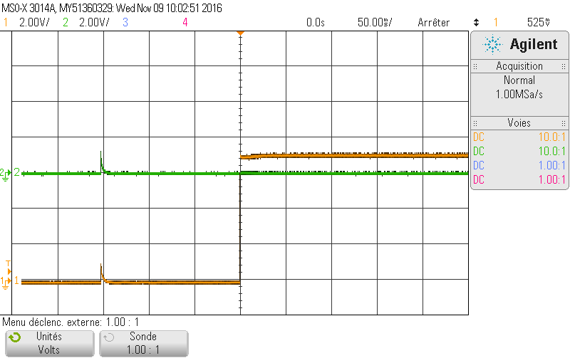
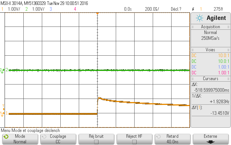
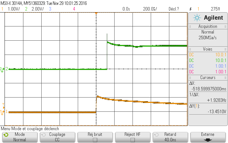
    Thank you for your answer. You can take a look at the outputs below.

    Here when the motor does not move :

    Here, when the motor rotate (I turn quilcky ON/OFF/ON) :

  • Hi user4509385,

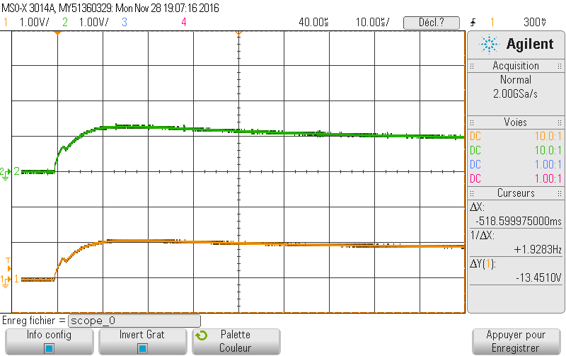
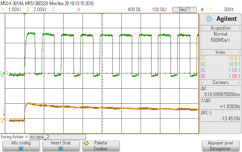
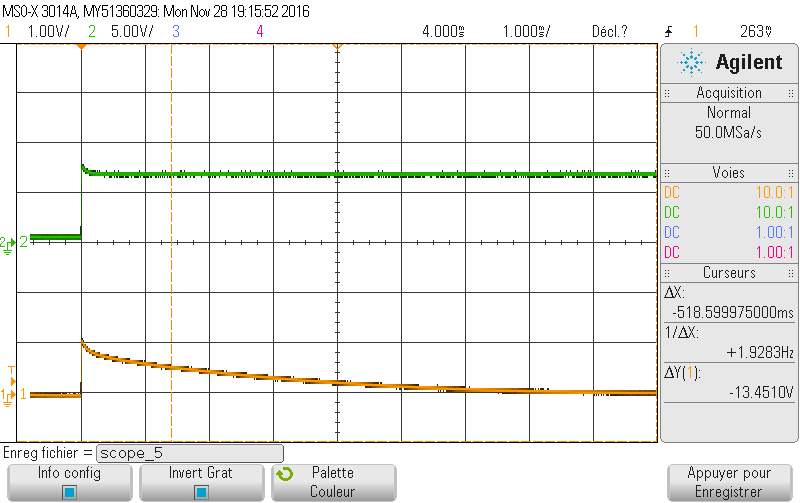
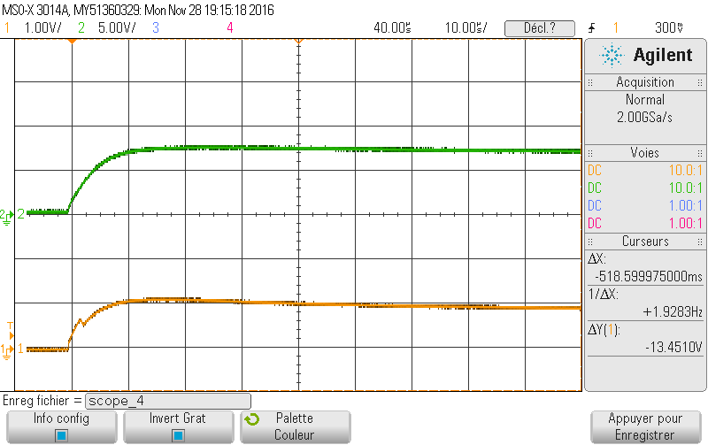
    What is channel 1 and channel 2 in the scope captures?
    If a fault occurs does the firmware disable the inputs?

    Can you zoom further when the motor does not start? 10us/div would be beneficial. With this it can provide hints to what occurred.

    Please add nFAULT to the scope capture also.

    Other signals to examine are VCC_CMD, nSLEEP, xIN1 and xIN2.
  • Hello Rick,

    Sorry for my late responce, I had some emergencies on other subjects.

    On the scope capture, channel 1 is A_OUT2, channel 2 is A_OUT1.

    I will try to do teh measurements tomorrow and post the captures soon.

  • Hello Rick,

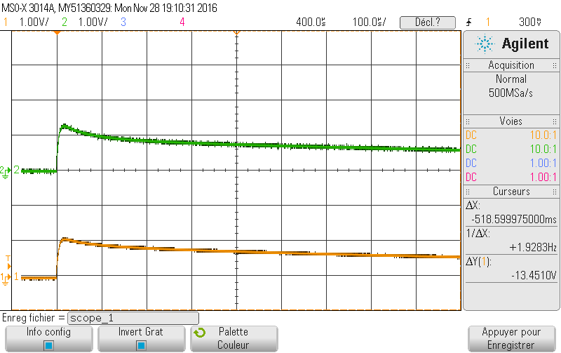
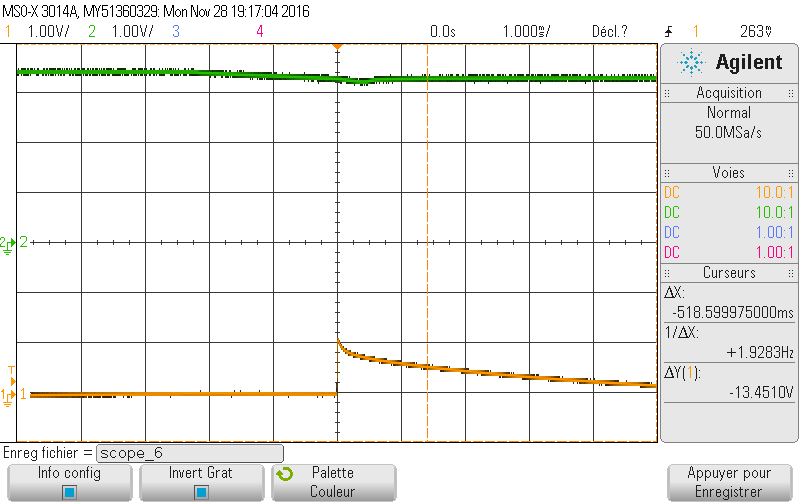
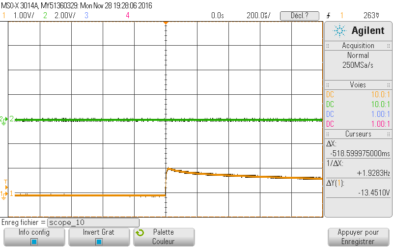
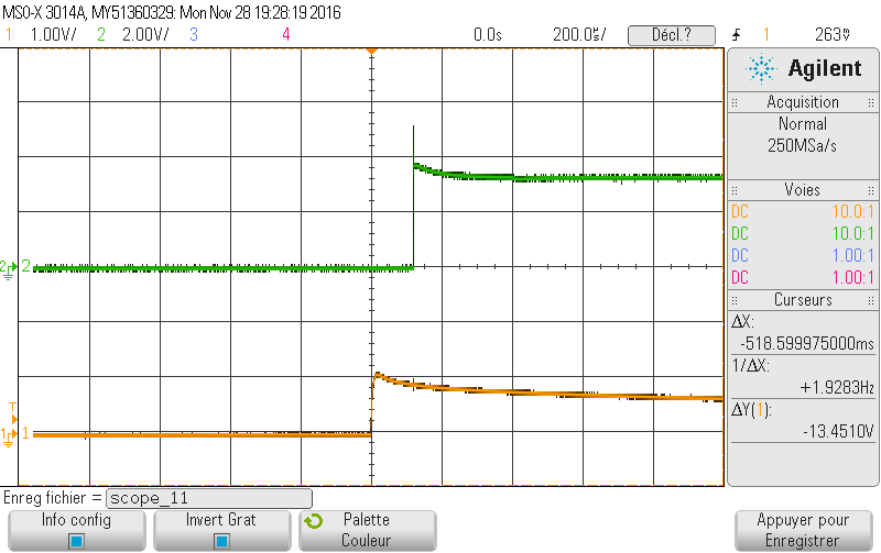
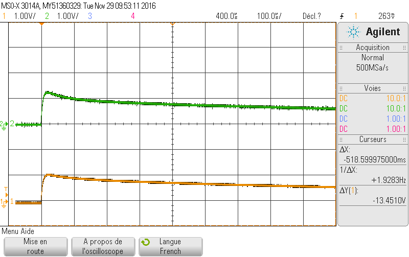
    Here are the captures :

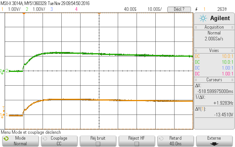
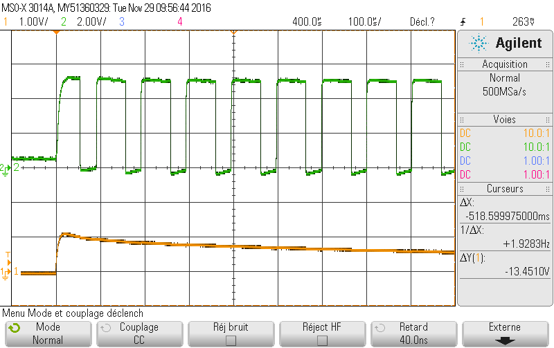
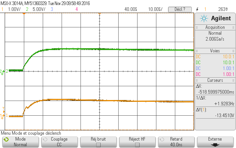
    Channel 1 is A_OUT2, channel 2 is A_OUT1 : 

    Channel 1 is A_OUT2, channel 2 is A_OUT1 : 

    Channel 1 is A_OUT2, channel 2 is nFAULT with a pull-up : 

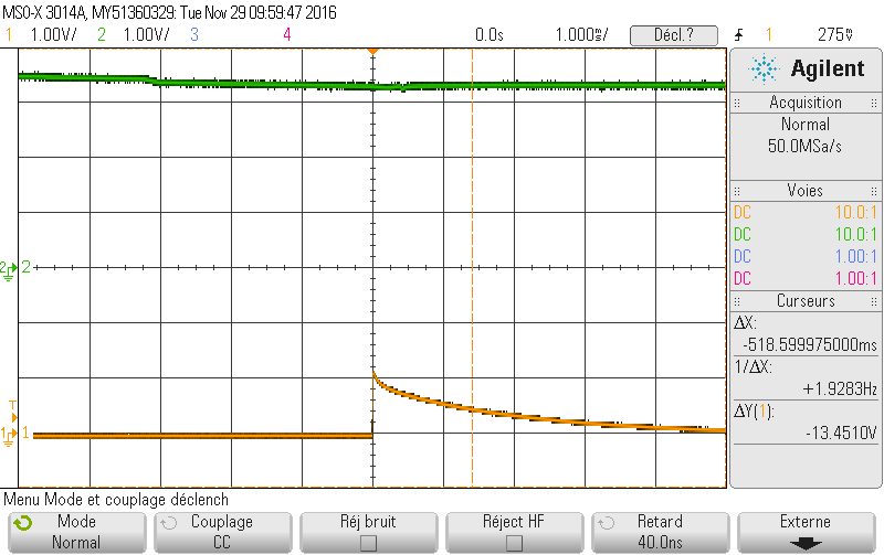
    Channel 1 is A_OUT2, channel 2 is VCC_CMD : 

    Channel 1 is A_OUT2, channel 2 is VCC_CMD : 

    Channel 1 is A_OUT2, channel 2 is nSLEEP : 

    Channel 1 is A_OUT2, channel 2 is A_IN1 :


    Channel 1 is A_OUT2, channel 2 is A_IN2 :

  • Hi user4509385,

    This is puzzling. There are several scope plots that are confusing.

    First is the toggling of nFAULT (low for 20us). There is no reason for this.
    Second is the ~1.2V on AOUT1 and AOUT2. This is typically an indication of the outputs being disabled (Hi-Z).

    Can you disconnect the motor and examine all inputs and outputs? Does the outputs function as expected?
  • Hello Rick,

    I did the measurments on inputs/outputs without the motor, and this quite the same :

    Channel 1 is A_OUT2, channel 2 is A_OUT1 : 

    Channel 1 is A_OUT2, channel 2 is A_OUT1 : 

    Channel 1 is A_OUT2, channel 2 is nFAULT with a pull-up : 

    Channel 1 is A_OUT2, channel 2 is VCC_CMD : 

    Channel 1 is A_OUT2, channel 2 is VCC_CMD : 

    Channel 1 is A_OUT2, channel 2 is nSLEEP : 

    Channel 1 is A_OUT2, channel 2 is A_IN1 :

    Channel 1 is A_OUT2, channel 2 is A_IN2 :

    It seems that with or without the motor, the phenomenon is the same.

  • Hi user4509385,

    Without the motor the device should operate correctly. Please double check your layout. If you have a second board please try it.

    If you do not have a second board, please report the VCP and VINT voltages when this event is occurring.
  • Hello Rick,

    It seems to work when I change the capacitor C15 from 2.2uF to 4.7uF.

    Thank you for your help !
  • Hi user4509385,

    We are glad to hear you have it working.

    A 2.2uF capacitor should have worked. Are you using a ceramic capacitor? Did you connect VINT to something that was not shown in the schematic?
  • Hello Rick,

    Yes, the 2.2uF and 4.7uF are ceramic capacitors. VINT is connected to nothing.

    But I guess that the track from the DRV8833 to the capacitor is a little bit too long (4mm).