This thread has been locked.

If you have a related question, please click the "Ask a related question" button in the top right corner. The newly created question will be automatically linked to this question.

DRV8302 Fault Pin

Other Parts Discussed in Thread: DRV8302, TMS320F2806, TMS320F28035

Hi everyone,

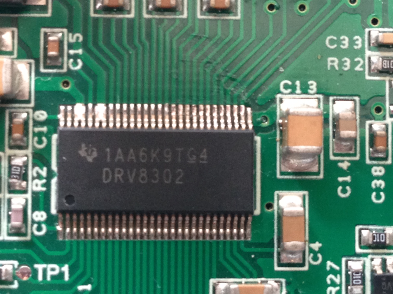
I am using a DRV8302 to drive a BLDC motor but DRV8302 Fault Pin always equal to zero. I share my drawing and measurement below;

I have run my circuit and  Code Composer program. while   EnableFlag=1, I have  observed the following values.

1) PVDD=25V
2) GVDD=11V
3) AVDD=7V
4) DVDD=3V
5) EN_GATE=3V
6) M_PWM=3.2V

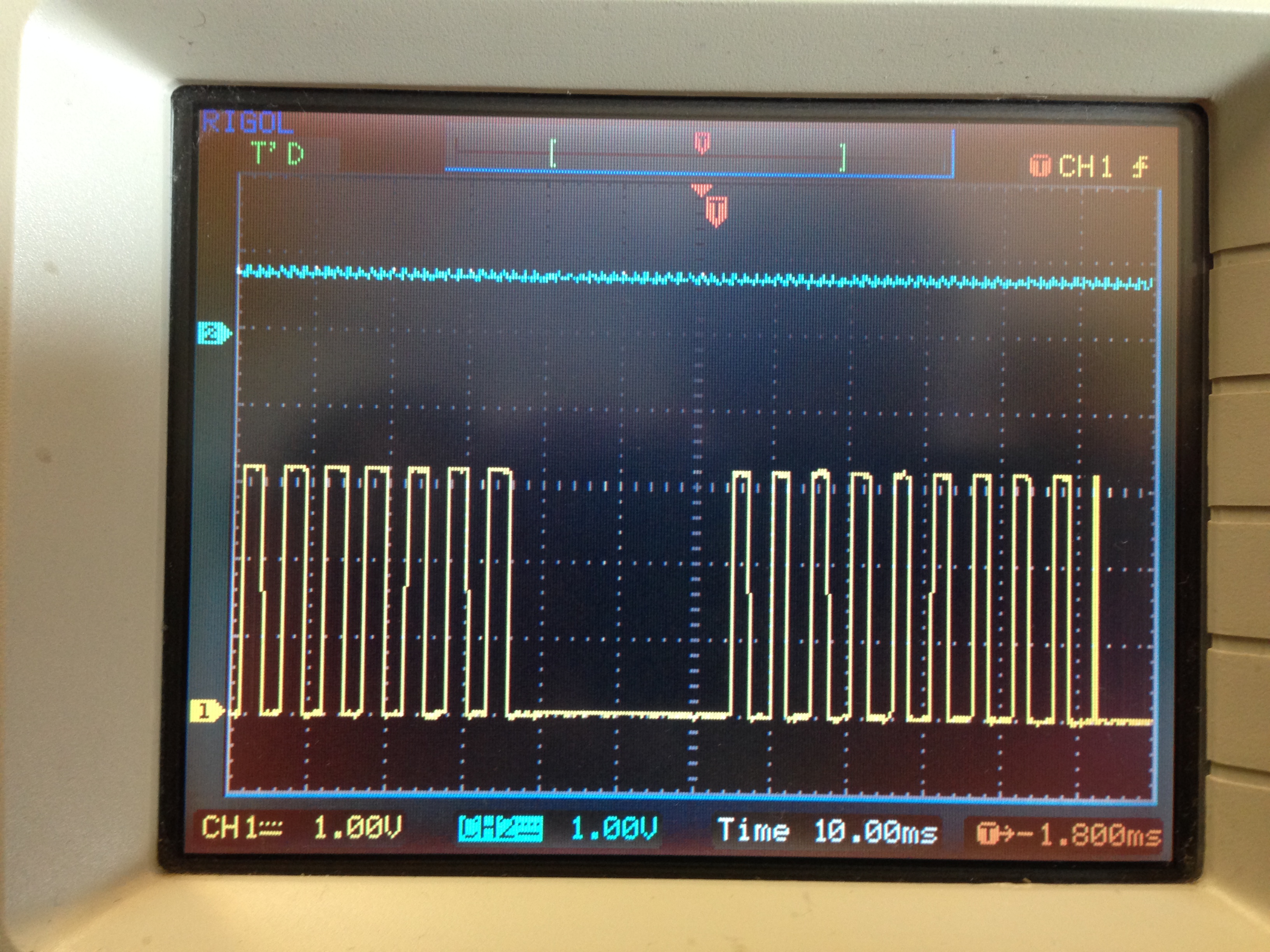
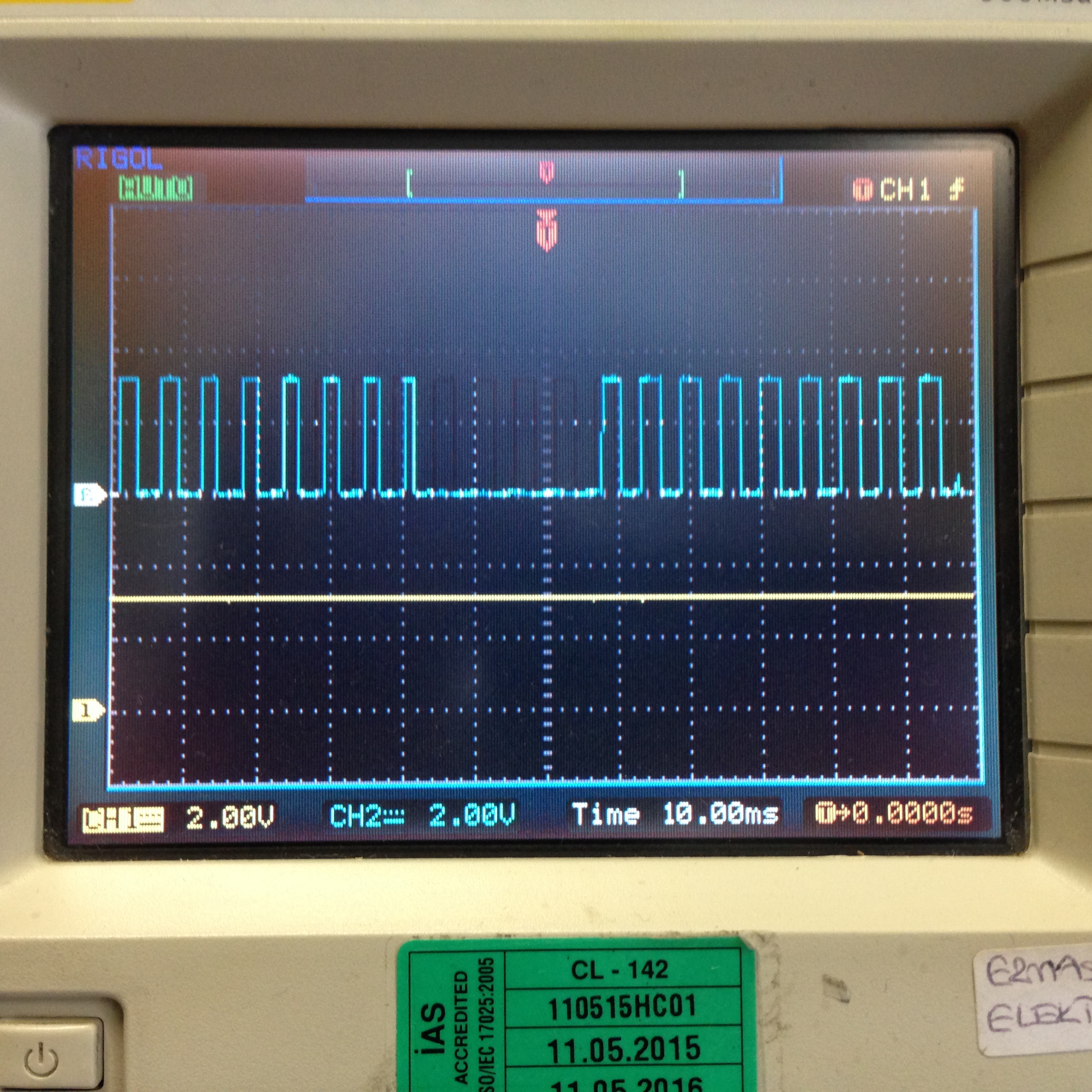
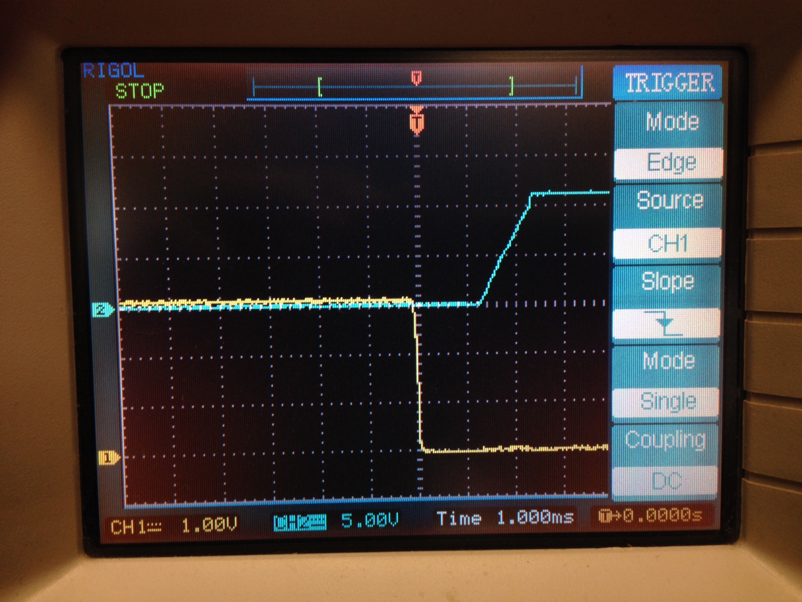
 INL_A=3.2V PWM  (I saw with an oscilloscope)

 INL_B=3.2V PWM (I saw with an  oscilloscope)

 INL_C=3.2V PWM  (I saw with an oscilloscope)

 INH_A=3.2V PWM  (I saw with an oscilloscope)

 INH_B=3.2V PWM  (I saw with an oscilloscope)

 INH_C=3.2V PWM  (I saw with an oscilloscope)

BST_A=11V

BST_B=11V

BST_C=11V

BST_BK=25V PWM (I saw with oscilloscope)

GL_A=0V

GL_B=0V

GL_C=0V

GH_A=1V

GH_B=1V

GH_C=1V

0447.Schematic.pdf

  • Hi Umit,

    Please provide scope captures of the inputs versus the outputs. The two inputs and two outputs pairs will be very helpful. INL_A, INH_A, OUT_A, GL_A, and GH_A

    Thank you.
  • Hi Rick,

    I observed the following results as you wish. Now, what can I do Rick?

    First picture for INH_A and GH_A

    Second picture for  INL_A and GL_A

  • Hi Umit,

    Thank you for the scope captures. I have asked a colleague for his comments.
  • Hi Umit,

    The driver does not appear to be responding to your inputs.

    Did you design your own PCB? Is it based off of an EVM design? Can you confirm this same issues on another PCB?

    Can you check for any shorts or open circuits? Can you confirm the PowerPAD is properly soldered?

  • Hi Nick,
    Thank you for your interest. We benefited from texas EVM design for brushless dc motor, I shared our drawing below.
    Meanwhile, I have a lot of same pcb so I will check our design for any shorts or open circuits. See you again.
    Best regard..
  • Hi Nick,

    I have many same pcb circuits and I observed the same mistake at all as I said. So I checked my circuits as you wish.

    No short circuit or open circuit. If you want, we can send our circuit and you can control our pcb because they are same with your design. So we use same component with you. We benefited  design below. Also we have it and we can run it with our brushless dc motor.

    sema.pdf

  • Hi Umit,

    Can you confirm the status of nOCTW. If nFAULT = 0 and nOCTW = 1 then several possible errors could be the root cause all related to the internal regulators. See page 18 in datasheet.

    Please measure the outputs of the DVDD, GVDD, and AVDD regulators and report. Please also double check the bypass capacitor values. Lastly, please double check the solder connect of the PowerPAD. Device GND is made through the PowerPAD so this is crucial.

  • Hi Nick,


    I controlled everything as you wish. Values of bypass capacitors are true and
    GVdd=10,9V
    DVdd=3,33V
    AVdd=6,62V
    I mean, all of them are true values.


    Also I controlled PowerPAD which is soldered to GND.So I want to share with you its pictures.
    If you agree and give us your adress, we want to send you our circuit. 


  • HI Umit,

    Thanks for the data. The regulators appear to be operating normally. I do not believe sending us the circuit is the best course of action right now.

    Did you confirm the value of nFAULT and nOCTW? Is nOCTW low as well? Can you confirm that nFAULT has a pull up resistor operating correctly?

    Please determine when exactly nFAULT goes low. Is it when power is applied, when EN_GATE is taken high, or when the INPUT is sent to the driver, etc. Please capture a waveform of this if possible.

    Can you provide the source layout files for review?

  • Hi Nick,

    I controlled nFAULT which has a pull up resistor operating correctly. When EN_GATE is taken high or when the INPUT is sent to the driver, nFAULT goes low.Also nOCTW is always high.

    When EN_GATE and INPUT are taken low, nFAULT and nOCTW are  high;

    When EN_GATE is taken high, nFAULT goes low; 

    When EN_GATE is taken high, nOCTW is still high; 

    When the INPUT is sent to the driver,  nFAULT goes low; 

    When the INPUT is sent to the driver, nOCTW is high; 

    Also I want to share our source layout files and their pdf below.

    3250.source layout files.rar

  • Also I want to share our source layout files and their pdf below.

    6646.source layout files.rar

  • Umit,

    Can you capture when exactly nFAULT goes low? How long after EN_GATE going high does this happen? Does it correspond to anything else in the system. In trying to get to the bottom of this, we need to trace it back to the error event.

    You can use the trigger function on most oscilloscopes to capture this.

  • Hi Nick,

    We would like to thank you very much for your interest and helping. 

    We captured when exactly nFAULT goes low according to EN_GATE  as you wish.


    Also we observed gate input of mosfet when EN_GATE going high.

  • Hi Umit,

    Thank you. The ENABLE and nFAULT look typical so far.

    On power up (EN_GATE set HIGH), the DRV8302 will hold nFAULT LOW until it finishes its power up sequence (~2ms). Can you capture nFAULT with DVDD, AVDD, and GVDD. Let us see how these regulators are powering up as these should be the only blocks that should issue nFAULT without nOCTW. You can use a 1ms time scale and trigger on the falling edge of nFAULT.

  • Hi Nick,

    We captured nFAULT with DVDD, AVDD, and GVDD.

    AVDD and nFAULT below.


    AVDD AND nFAULT below..

    GVDD and nFAULT below..

  • Hi Umit,

    Thank you for the timely response and wave forms. From these it appears all the regulators are successfully powering up....so the mystery deepens...

    Is the buck regulator functioning properly?

    What is the value of the nFAULT and nOCTW pull up resistor? Can you verify that there is no chance the MCU is driving this pin LOW (just to rule this out). Though the gate driver should still respond to inputs if this was the case.

    How many boards have you examined with this same failure? Where was the DRV8302 sourced from?

    Is there a chance the DRV8302 was exposed to air for an excessive time before assembly? The DRV8302 has an MSL 3 rating.

    www.ti.com/.../quality

    http://www.ti.com/lit/an/spraby1/spraby1.pdf

    Just trying to rule out all possibilities.

  • Ok, I have been having the same issues. everything looked correct but this fault pin was kicking in all the time. I separated digital circuit and motor powers and realized that whenever motor voltage is above 4v then fault kicks in (it was dependent on input pwm duty-cycle aswell).
    I almost destroyed my board by cutting and changing tracks when debugging (it took me almost two weeks to debug it). Finally, I got it working and thought It might be helpful to you too.
    the problem was distance between ground pad of DRV8302 and source of low side mosfets (which are connected to the ground). in my board, distance of ground pad to mosfet's ground was like 1-1.5 inch (7mm thick) since I couldn't rout it closer. So I soldered a very thick wire from top between sources of mosfets and ground pad of drv8302 and used a wire as short as possible (maximum distance of pad to mosfet ground is 1cm now) and It works well.
    I couldn't believe how sensitive it is to this connection. at first I used a bit longer wire it improved the result but fault was still kicking in when I increased the motor voltage to 10v.
    this is actually my first time having trouble with my design because of layout rather than schematic. but it was good lesson I think.
    looking at your board it seems like you have much longer distance than mine in which even a wire connection might not help. You might want to try making a new layout with low side mosfets as close as possible to drv8302 with shortest paths on ground connections.
  • Hi Nick,
    I controlled that buck regulator functioning properly. Value of the nFAULT and nOCTW pull up resistor are 10K.
    I cut off copper connected to microcontroller. it still goes zero.
    I've tried 5 circuit with same error so far. We have no idea about the DRV8302 because we supply from china.
    What do you think we should try another, this is important for us??
  • Hi Sina,
    Thank so much you for advice.
    As you said, we have much longer distance than yours so we need to new circuit for this condition+ but firstly we want to try all possibility .
  • Hi Umit,

    In response to Sina's comment, can you try soldering a thick wire from the GND of the MOSFETs/power supply to the GND of the DRV8302? 

    Concerning the DRV8302 status, can you try sampling a few devices from ti.com or other distributor and trying these as a replacement device. This may give a clue to as whether there is a fundamental PCB error or some issue happened in assembly of these PCBs.

  • Hi Nick,

    We soldered a thick wire from the GND of the MOSFETs/power supply to the GND of the DRV8302 and nFAULT still goes zero.

    I want to share our DVR8302 code on the picture below. Can you check  this series? Also we'll give the new order.

  • Hi Umit,

    Will do. Please allow a day or two.

  • Hi Umit,

    These devices are quite old. They were shipped in 2011. Please look at sourcing new devices and replacing on the PCBs.

  • Hi Nick,
    We ordered new DVR8302. We will solder it and give you information about that.
    Also I want to ask new question. We use TMS320F28035 but some friends recommend TMS320F2806 as a new version.
    Do you have any idea or recomend?? What would be better ??
  • Hi Nick,
    We soldered new DRV8302 today but nFAULT pin goes to zero again. We have a MARS 4201(ETEK) brushless DC motor and we want to produce AGV. That's why, we will design new board and we want to new version TMS320F2806x. Do you have any idea or recomend for us?
  • Hi Nick,

    We want to start new design, we are waiting for your reply.  What do you think about  TMS320F2806x  or  can you give us some advice?

  • Hi Umit,

    You would be better off posting to the C2000 forum for TMS related questions. They will have better experience and answers.

  • Hi Nick,
    We are very pleased with your help o thank you very much for all your help.