This thread has been locked.

If you have a related question, please click the "Ask a related question" button in the top right corner. The newly created question will be automatically linked to this question.

DRV8842 VREF pin problem with V3P3OUT * (2K / 3K)

Other Parts Discussed in Thread: DRV8842

Hi.

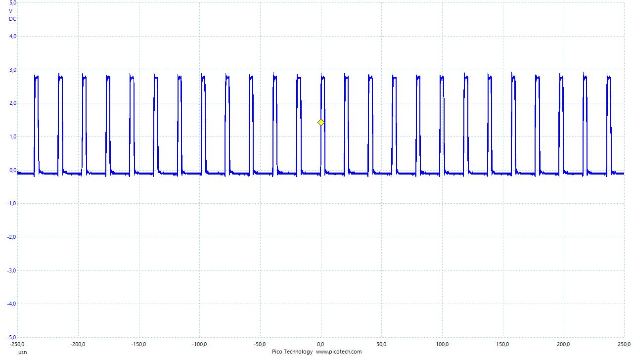
We are trying to control 24V 65W DC motor with DRV8842. I can controlling motor with 100kHz PWM and can change direction with EN/PHASE interface but the speed of the motor is not enough. First I've set the current limit inputs to 80% and put the VREF pin ~2.2V with 1K pullup and 2K pulldown but I can't see the 2.2V or near on the VREF. I'm just seeing ~0.25V on VREF. V3P3OUT is actually 3.3V. I've attached circuit and PWM + motor output waveforms in a 7zip filehttps://e2e.ti.com/cfs-file/__key/communityserver-discussions-components-files/38/drv8842.7z.

  • Hi Orkun,

    Please double check your resistors. Is it possible one the 2k is incorrect or damaged?

    Also, using a 3k pulldown is slightly below the recommended minimum value. This combination will load the regulator with 1.1mA. Please consider raising the resistor values.
  • Hi Rick,

    I'm going to change resistors with 10K (for VREF-GND) and 5.1K (for VREF-V3P3OUT) so it will pulldown the V3P3OUT with 15.1K then I'm going to write the result.

    Thanks.
  • I've changed the resistors and it's ok now. Thank you Rick.

  • Hi Rick,

    I have another problem about DRV8842 again. Now I'm giving all I0..I4 pins to logic 1 (I tried with both 3V and 5V) and I'm applying 100kHz PWM to IN1 and driving IN2 to logic 0. I'm expecting that the motor needs to use about 4A (2.05 / (0.5) = 4.1A) but when motor is under load (applying force with my hand when it's running) it's going up just 1.4A. I'm using 24V, 4.3A DC motor and I want to control it's speed and also it's position. And when I connect it a gear and connect them a belt it's going slower than a turtle.
  • Hi Orkun,

    Have you tried running the motor without PWM'ing to get a baseline.

    For a simple experiment, please try the following:
    1) Set the decay mode to slow decay
    2) Set IN1 to a logic 1 and IN2 to a logic 0.
    3) All other inputs remain the same as you have them.

    This should cause the motor to run at 100%. The motor current will be chopped at 4.1A due to the chopping circuit.

    Once you get the baseline, then you can try the PWM input. Typically the PWM frequency of a brushed motor is 10kHz to 30kHz. I suggest you try in the 30kHz region and adjust up or down as necessary.
  • Hi Rick. I'm also doing same as you said. But it is still same under force. I'm giving directly logic 1 to IN1 and 0 to IN2 and all I0..I4 to logic 1. I've removed the driver (DRV8842 circuitry) and plug Motor directly to supply then it moved very fast. I'm confused. Thanks.

  • Hi Orkun,

    What are the specifications of the motor? (model #, R, L, I)?

    When running with IN1=1 and IN2=0, please look at the outputs to determine if the output voltages are PWM'ing.
    Can you provide scope captures of the outputs?
  •  Hi Rick. R=1.6ohm bUt I cannot measure the L and am out now I=4.3A for motor. ı have disconnected the sense resistor it is going fast as direct supply connection.

    Edit: R=11.6 Ohm, L=4.4 mH, Rated current is 4.3A motor model SanMotion t406 type motor from sanyo denki

    I think, probably current sense circuitry in the controller cannot sense the voltage drop on R_Sense because it is 100 times smaller than the armature winding resistor. I think I need to increase the R_Sense resistor up to 1 Ohm or more.

    Image is the output waveform when IN1 is 1 and IN2 is 0, slow decay with 0.1 Ohm R_Sense resistor.

  • Hi Rick and everybody :)

    I've solve it with decreasing the R_sense down to 0.025Ohm and now I can reach the 3 A. Thanks.
  • Hi Orkun,

    Raising the sense resistor to 1 Ohm is not a good idea. This will violate the absolute maximum ratings of the ISENSEx pins when more than 800mA is flowing through the resistor.

    The device is driving current for approximately 5us, then switching to slow decay. There are a few of possible reasons for this ( in order of ease of checking):
    1) The VREF voltage is lower than expected, or the sense resistor is higher than expected or wirewound.
    2) The current limit is exceeded to enter current regulation. This may be caused if there is a capacitor across the motor terminals.
    3) Noise on the sense pins is causing this behavior.

    If you are using a wirewound resistor, please switch to a film resistor or multiple resistors in parallel to achieve the wattage.
    If you have access to a current probe, please zoom in on the 5us where the output is high to measure the current. If it approaching the 4A regulation setting, look for a capacitor or some other reason the current is that high. You can also measure the voltage across the sense resistor to get the same information.
    I don't suspect noise at this time because the events are repetitive, but cannot rule it out.