This thread has been locked.

If you have a related question, please click the "Ask a related question" button in the top right corner. The newly created question will be automatically linked to this question.

Trouble using external PWM with DRV2603 Evaluation Board

Other Parts Discussed in Thread: DRV2603

I’m having trouble using an external PWM to drive an LRA using the DRV2603 Evaluation Board.

Using binary counting Mode 5 (LEDs: 00101), I press button B2 to Enable the DRV2603. The external enable signal works correctly; when I toggle it on and off, the LRA turns on and off. However, I supply an external PWM signal and no matter what the signal looks like (0% to 100%), the signal driving the LRA doesn’t change (measured by oscilloscope attached to OUT- and OUT+). I have removed the JP1 jumper. My PWM signal is 3.3v and 10kHz frequency and the board is powered with 5v from a USB connection. This seems to be OK given what I read in the datasheet [External PWM Voltage, VPWM' (optional): 1.8V to VDD]. I manually change the external PWM (from 0% to 100%), confirmed with oscilloscope reading, and the signal to the LRA doesn’t change. I also tried using a high and low signal as the external PWM to simulate 0% and 100% PWM but the LRA vibration does not change.

I’ve also tried this with an external LRA (https://catalog.precisionmicrodrives.com/order-parts/product/c10-100-10mm-linear-resonant-actuator-4mm-type) and removed the JP3 and JP4 jumpers and the result is the same.

In an attempt to troubleshoot further and disconnect the MSP430 from the DRV2603, I removed resistors R1 and R8 and shorted resistor R2 as suggested on pages 10 and 11 of the DRV2603 Evaluation Kit User’s Guide. The result is the same. I also test this using binary counting Mode 3 (LEDs: 00011) and pressing button B2 and the results are the same (external enable works presumably since I removed resister R8, external PWM doesn’t work).

Do you have any suggestions for getting the external PWM signal to drive the DRV2603? This seems like it should be straightforward but I can’t seem to get it to operate given the instructions in the User’s Guide.

Thank you!

  • Hi, Daniel:

    I am think this probobaly is caused by the PWM input frequency.
    currently, i don't have a DRV2603EVM at handy. i am trying to get one in about two weeks.

    can you increase the PWM frequency? such as use 30kHz PWM input.
    let's try and find out.

    Thanks.
  • Hi Peter,

    I tried increasing the PWM input frequency and the problem remains. No matter what the PWM input looks like, the OUT signal does not change. The Enable signal still works. Do you have any other ideas?  

    Thank you,

    Daniel

  • Hi, Daniel:

    I am out of ideas.
    can you post a scope capture of what you see for this test?

    do you check the output waveform after a low-pass filter?

    Thanks.
  • Hi Peter,

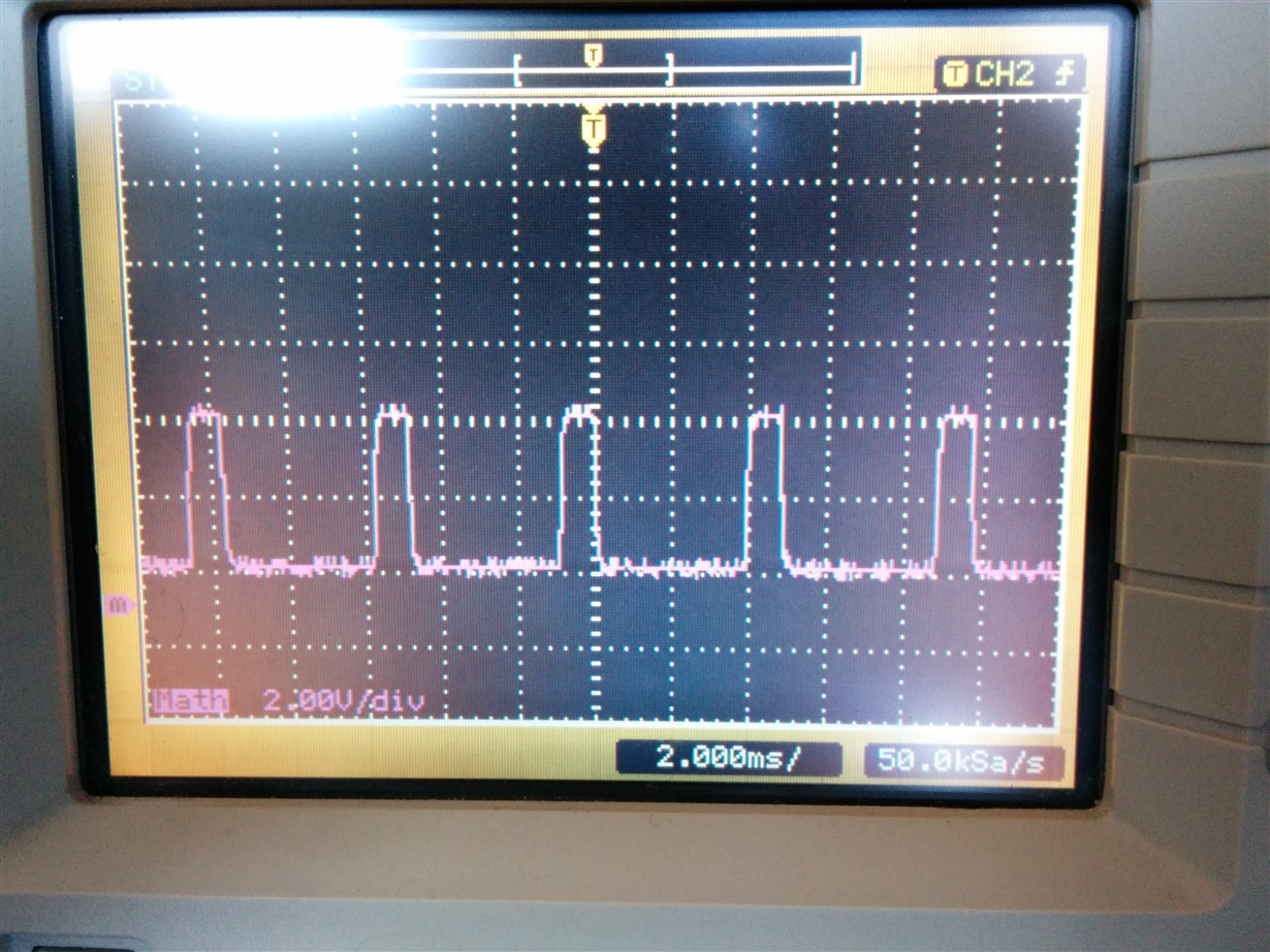
    Here is a photo of the output waveform after a low-pass filter:

    Does that output look OK? Again, if I change the input PWM, this signal does not change at all. I checked the signals going into the DRV2603 at the pads and they all look good (Enable toggles on/off, PWM carries the PWM signal I generate, ERM/LRA is drawn high). 

    If you have any further ideas, please let me know.

    Thank you!

    Dan

  • Hi, Dan:

    i think there is some misunderstanding.
    the low pass filter cut off frequency should be 1kHz.

    for LRA (Linear resonance actuator), the drive signal is a AC signal.
    for measurement, we need to add a low pass filter to each channel (OUT+, OUT-), and use math function(minus) to get a differential drive output.

    from the scope capture, it looks like a 20kHz PWM, which is the carrier PWM frequency.
    please refer to the test setup in the data sheet, and also Figure 2 for what a common lRA driver signal looks like.
  • Hi Peter,

    I think my setup was OK except I was using 3kHz as the cut-off frequency for a digital low-pass filter (the manual suggested using 1 - 3.5kHz). I've changed it to 1kHz. I've connected the oscilloscope probes to the OUT+ and OUT- channels (which already have low-pass filters integrated) and then used the math function on my oscilloscope to output the signal I sent in the last photo. I also use a digital low-pass filter on the scope. 

    With the 1kHZ cut-off frequency this is what I'm getting (traces from top to bottom: OUT+, OUT-, Math (1-2)):

    And here is my setup (inputs to PWM and ENable, oscilloscope probes attached to OUT+, OUT- and GNDs, LRA attached to OUT):

    Thank you,

    Dan

  • Hi, Dan:

    it looks like an ERM drive waveform, not LRA drive waveform.
    can you check the configuration pin of DRV2603?

    Thanks
  • Hi Peter,

    I confirmed that the configuration pin is set HIGH which seems to be the correct setting to select for the LRA mode. I'm going to order a few of the DRV2603 chips and try building my own board to see if I have better luck. Maybe the evaluation board I have is defective.

    Thank you,
    Dan

  • It seems there is something wrong with the Evaluation Board we received. We put together our own board with the the DRV2603 and it works just fine to drive our LRA.  Thank you for your assistance.

  • Hi, Daniel:

    Glad to know it works.

    Thanks.