This thread has been locked.

If you have a related question, please click the "Ask a related question" button in the top right corner. The newly created question will be automatically linked to this question.

DRV2603 Not Working

Other Parts Discussed in Thread: DRV2603

Hello, 

I have been trying to implent a haptic feedback using the DRV2603 however I couldn’t get the vibration motor to turn on.
The input PWM frequency is 10.9KHZ 

I have verified that the Enable is pulled high before I send the PWM to the DRV2603 and I also disabled it after the PWM trail is finished.

Here is a pseudo code on the micro controller side:

  //ENABLE MOTOR DRIVER SIGNAL
    output_high(PIN_A4);
   //PWM OUT
    set_pwm1_duty(85);
     delay_ms(200);
     //turn off motor
   set_pwm1_duty(0);
   delay_ms(1);
   //DISABLE MOTOR DRIVER
    output_low(PIN_A4);
     delay_ms(10);

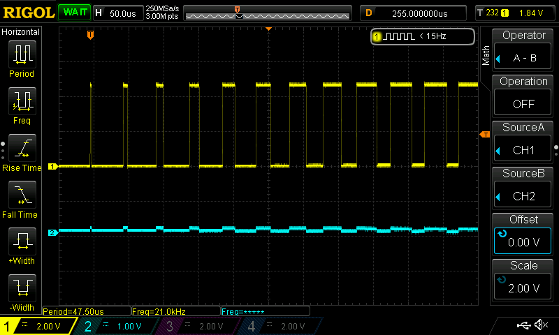
Here is a scope shot of the input PWM ( yellow) and output waveform ( blue)  on one of the motor output terminal.

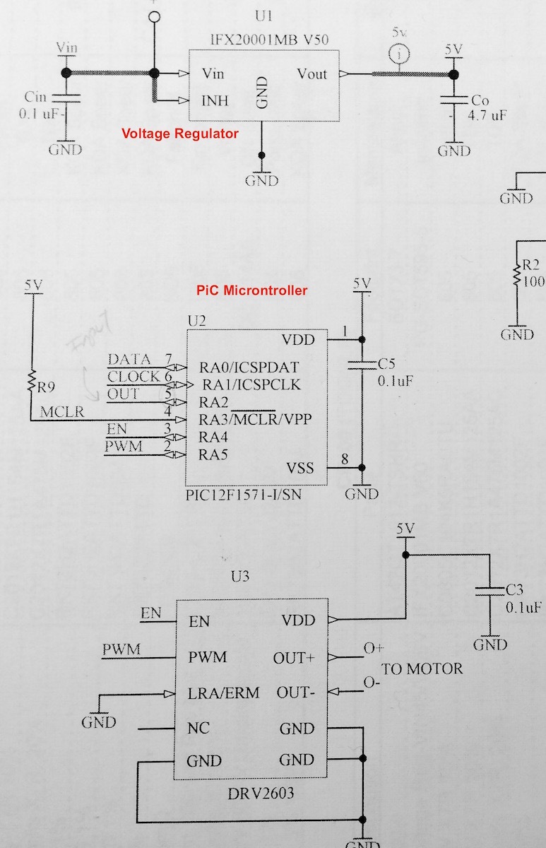
Any idea what I am doing wrong? I am also including the schematic below. I appreciate your input. Thank you !

DRV2603

  • Karl,

    Can you provide me with the ERM part number being used?

    From the looks of the output waveform it appears as though the motor is trying to go but it does not have enough power going through it. I would recommend running the motor at a higher duty cycle, maybe around 95%.

    Also, I would recommend monitoring the input voltage (VDD) to make sure that there are not any issues coming from the supply power.

    Best Regards,

    Javier Palomo

  • Hi Javier, 

    Thank you for the quick reply. 

    The motor supply power is the same as the supply to the micro controller and as you can see from the scope shot the output PWM remained 5v, so there wasn’t a dip in supply voltage.

    I disconnected the motor and have tried powering it directly from the voltage regulator and ran fine.

    I then removed the voltage regulator output and powered the circuit from a 5v lab power supply that can supply ample of current and the motor still didn’t run. 

    The motor I bought from eBay, I don’t have a part# here are the motor specs:

    Motor specifications: 4 * 4.5 MM (after removing the shell it is a coreless motor 4 * 8)
     
    Motor Length: 8 MM (excluding eccentric)
     
    Eccentric wheel size: 3 * 3.5 * 3.8 MM
     
    Voltage: 1.5 V Current: 60 MA
     
    Voltage: 2 V Current: 80 MA
     
    Voltage: 3 V Current: 115 MA
     
    These motors are brand new original coreless small vibration motor, and the workmanship is very nice. And its technical accuracy, nor is it generally small factory can produce.
     
    It's rated voltage is 2V, operating voltage range is 1.5V-3 V this. It 3V when vibration forces should be better than 1.5V at large, but also relatively easy to heat. Buyers should decide to use that kind of voltage according to their needs.


  • Karl,

    Is there any information on who the manufacturer of the ERM is?  Although the motor specs will help, it would be ideal to have a datasheet from the manufacturer.

    Nevertheless, after taking a look at the motor specs I am thinking it could the supply current. I will go ahead and test it out on a 20 Ohm load and see if I can get the required supply current for the motor.

    Best Regards,

    Javier Palomo

  • Hi Javier,

    Thank you for the offer to tested it out, I really appreciate it.

    That’s all what the seller provides, specs without a datasheet. Is there a specific information that you’re looking for? maybe I can ask.

  • Karl,

    No worries, I just wanted to check if I happen to have one of the ERM’s on hand. I would contact the seller asking to provide more information on the manufacturer of the ERM’s as well as a datasheet.

    I did run the test on the DRV2603 with a 25 Ohm resistor acting as the load and I was able to pump 124mA at 3.1V, and I was able to run it on an ERM with similar results. Given that this meets the operating requirements, I am not sure as to why the ERM’s are not running off the driver.

    Are you able to get any output out of the DRV2603 driver?

    Best Regards,
    Javier Palomo
  • Hi Javier,

    If  i disconnected the motor I got a pwm output ( Full VDD) . I will try to capture it on the scope and send it to you. 

    Is the driving PWM frequency an issue, I am using 10.9 Khz?

    Thank you

  • I am going to replace the haptic controller and find a new ERM to see if that makes a difference.

    Here is the screen shot of the haptic controller no load output ( Out + && Out-) 

  • Karl,

    Correct me if I am wrong but the yellow wave form is the input PWM signal and the output math function (Out+ minus Out-) is the blue waveform?

    Regarding the frequency of the PWM signal, although you are operating within the PWM input frequency range sometime the given actuators have to operate at higher frequency to get enough acceleration. Since we are limited with information from the ERM, try increasing the PWM input frequency to see if we get any positive feedback.

    We will know if we are getting a correct output if you see a PWM signal as shown in the graph below:

    Best Regards,

    Javier Palomo

  • Hi Javier,

    The yellow PWM is on one leg of the motor terminal. The blue waveform is on the second motor terminal. They don't look like what is shown on the datasheet and that is way I am also concerned.

    I replaced the DRV chip and I am still having the same problem. I also replaced the motor ( the new motor draws 100mA at ~ 3.3v)-no datasheet for this one either.  I know the onboard voltage regulator can't supply that much current so I disconnected it and supplied a 3.3v directly from a bench power supply. The motor won't even turn.

    It could be the PWM frequency but it's within the limit so at least I should see some movement. I also have tried to increase the PWM to 200ms maybe it should go for longer?

    I will try to experiment some more. It got frustrating but I will do my last try with PWM frequency and duration.

  • Karl,

    Your waveforms Out+ and Out- look to be correct, however, I noticed that the your Out+ is trying to drive the ERM at almost 5 volts. Is there a reason as to why it is driving that high (could be I misread the scale)?

    Given that your schematic is correct (tying LRA/ERM pin to GND, PWM/EN to MCU, and the 0.1uF cap on VDD), I can only assume that it is the PWM signal coming into the driver. Lets try and remove the PWM input and just run the ERM using the enable pin as described below from the datasheet.

    Best Regards,

    Javier Palomo

  • Javier,

    Sorry for the late reply, I tried removing the PWM and that worked! thank you very much for the tip.

    So now I know it’s the PWM frequency that is causing the driver not to work. I will try increasing it and I hope this should fix it. 

    Thanks again

  • Karl,

    No problem, happy to help!

    Best Regards,

    Javier Palomo