This thread has been locked.

If you have a related question, please click the "Ask a related question" button in the top right corner. The newly created question will be automatically linked to this question.

DRV8303 GVDD_UV after successful operation

Other Parts Discussed in Thread: DRV8303, DRV8301, DRV8303EVM

Hello,

We are students at Michigan Technological University and are having issues implementing the DRV8303 chip to drive a 300W PMAC motor.  After populating our board and doing several safety checks, we successfully operated our motor with trapezoidal control under open load conditions.  We attempted to use sinusoidal code to run the motor and received 0x0600 back from status register one.  Now, when attempting trapezoidal control again, the same error occurs.  Here are the steps we took:

1. Trapezoidal commutation with default control register settings.  This worked without any errors in the status registers; however, when applying load to the motor, could stall so GATE_CURRENT was changed to peak 1.7A and OC_MODE was changed to report only (0x13E0 was sent).

2. Trapezoidal commutation works with changed settings.  Now, when applying load to the motor and stalling, the motor would continue operation after the load was lifted.  During this operation, overcurrent was reported on one of the FETs under stall conditions and then status register read 0x0000 after the load was lifted (as intended).

3. After trapezoidal control was working as expected, we changed to sinusoidal control.  The only difference in status registers was changing PWM_MODE to 1 (sent 0x13E8).  This time, we received 0x0600 out of the status register and immediately stopped operation.  We had used the sinusoidal code on the DRV8301 BoostXL board and had no issues, so this was concerning.  We checked the FAULT line and it remained low during this operation (~40 mV); unfortunately, we did not check the voltage of GVDD.

4.  Next, we decided to retry trapezoidal commutation to ensure that was still working.  Unfortunately, the same status register response occurred, 0x0600.

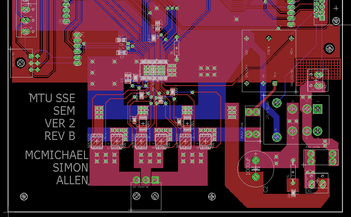
Due to the nature of the event, we believe this is a software error as all the hardware was working properly with trapezoidal control.  We can post snippets of our code and board layout if that will help addressing what happened and how we can fix this issue.

  • Hi Andrew,

    When you get a chance please measure GVDD and report the value. Also please report the DVDD and AVDD voltages.

    Can you provide your schematic?

    When running in 6 PWM mode, are you adding dead time between the high side and low side through firmware? This could be one difference.
  • I can measure those values in 3 hours, however, here is the schematic, board layout, and a snippet of our code which handles the hall effect from our motor, and our main.c file as well.  The hall code is interrupt based.

     Sample Code.hBLDC_v2.brdBLDC_v2.schmain sample code.h

  • Measurement results in trapezoidal mode:
    GVDD: 1.31 V
    DVDD: 3.35 V
    AVDD: 6.65 V
    PVDD: 44.1 V

    I know GVDD is way lower than it is supposed to be. At this point, we are looking for what caused this failure in order to prevent it happening again.
  • Hi Andrew,

    Agreed, we would like to prevent it in the future also. It is recommended to use the overcurrent protection. It could be an indication of why the device was damaged.

    There are a few things to try based on the schematic. After the device is replaced:

    1) You can use a power supply and lower the current limit to determine if there is a possibility for shoot through.
    2) Look at the GVDD for spikes that could damage the pin. The ground path is longer than is recommended. Please note the layout guideline section of the datasheet.
    3) As mentioned, the dead time in 3PWM mode is set to the DTC setting (50ns). Did the firmware add some additional dead time? If so, please consider changing the DTC resistor to account for that.
  • Thanks for your advice. We will replace the device tomorrow. We will add the current limits again to check for shoot through and monitor spikes in the GVDD line. There was no dead time added for the trapezoidal code. For future revisions of our pcb, what is the maximum distance you recommend from the DRV8303 GVDD capacitor to ground?
  • Hi Andrew,

    Does the code or PWM change both inputs on the same instruction or clock in 6PWM mode? Sometimes this is not obvious, but there can be a one or more internal clock delay.

    Please refer to the DRV8303EVM documentation for a working example of the layout.  The hardware files can be found HERE

  • Hello,

    We got our motor controller working well, but we are running into problems with the charge pump blowing in the DRV8303. The resiliency of the charge pump seems to be a function of the switching frequency, the power flowing through the FET's, and the gate current level. Basically we think we are operating above the max switching frequency at our current switching frequency and current.

    Is there any way you can provide the max switching frequency at each gate current level (0.25, 0.7, 1.7 Amps) so that we can appropriately set our switching frequency?
  • Hi Andrew,

    Have you confirmed that you are in compliance with equation 3 of the datasheet?

    The gate drive supply (GVDD) of the DRV8301 can deliver up to 30 mA (RMS) of current to the external power
    MOSFETs. Use Equation 3 to determine the approximate RMS load on the gate drive supply:
    Gate Drive RMS Current = MOSFET Qg × Number of Switching MOSFETs × Switching Frequency (3)

    What FETs are being used in your system?
  • We are using CSD18540Q5B FETs with Qg of 41 nC.  Using equation 3:

    Gate Drive RMS Current = (41 [nC]) * (6 [# FETs]) * (16.8 [kHz]) = 4.13 mA.

    It might be important to note that we have also used a switching frequency of 4.2 kHz which stalled the motor and caused no damage to the DRV chip. 

  • Hi Andrew,

    Was the charge pump damaged when using a switching frequency of 16.8 kHz?

    What switching frequencies caused damage in your system?
  • Correct, the charge pump was damaged after using a switching frequency of 16.8 kHz. This is the only switching frequency we've tested in our actual system.
  • Yes, the charge pump was damaged at a switching frequency of 16.8 kHz. That is the only switching frequency that has been used in our application
  • Hi Andrew,

    It should be noted that both the current through the power MOSFET and gate drive current will effect the parasitics of the output MOSFET stage. Typically these manifests as transients voltages either under or overshoot that can cause damage to the MOSFET or gate driver.

    I would recommend using an oscilloscope to observer the switching node of the half-bridges while you modify these parameters to see what the effects are.

    This is typically combated by improving the layout design, lower switching speeds (lower gate drive current), snubbers, schottky diodes, local capacitances, etc.

  • Hi Andrew,

    How can you made the DRV8301 working well? My DRV8301 board has the same problems as yours.
    EN_GATE=1; EN_GATE=0
    GVDD: 1.33V 0V
    DVDD: 3.3 V 0V
    AVDD: 6.6 V 0V
    PVDD: 16 V 16V

    My DRV8301 board can output PWM signals when the chip of DRV8301 is paded, but then begin to fault, the status register said : GVDD_UV.
    I change the DRV8301 with a new chip, it working well at the first time, but then it go to fault : GVDD_UV.
  • Hi,

    Your question has been replied to HERE