This thread has been locked.

If you have a related question, please click the "Ask a related question" button in the top right corner. The newly created question will be automatically linked to this question.

Regarding Insta spin boostxl drv8031 controller and driver card with gui interface

Other Parts Discussed in Thread: BOOSTXL-DRV8301, DRV8301, LAUNCHXL-F28027F, INSTASPIN-BLDC, LAUNCHXL-F28069M

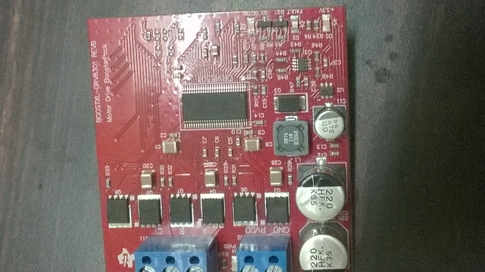
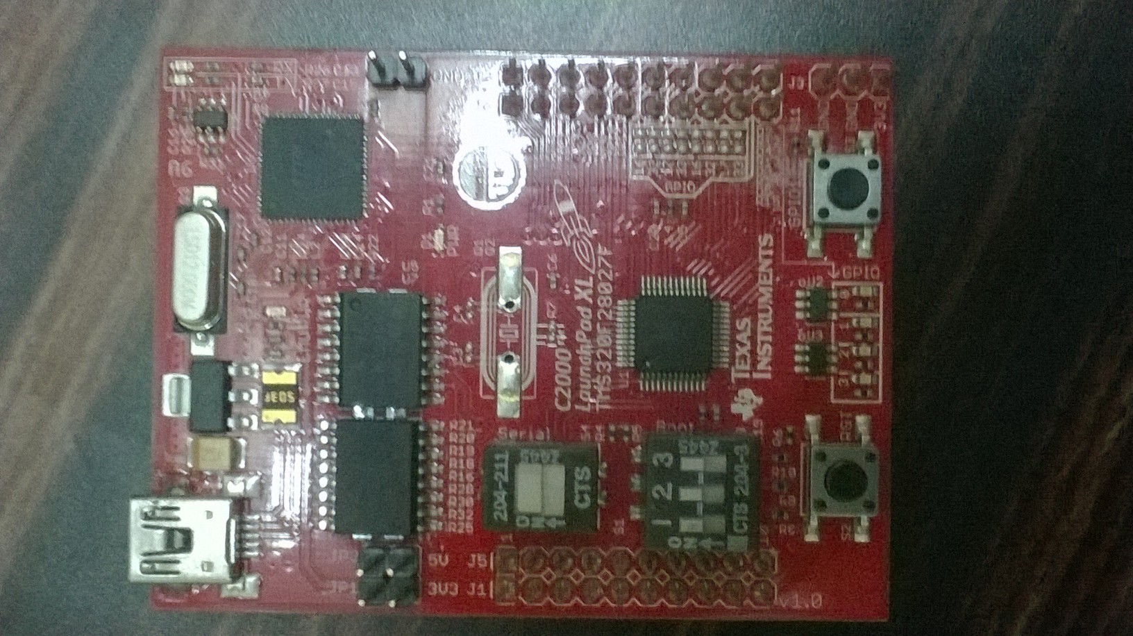
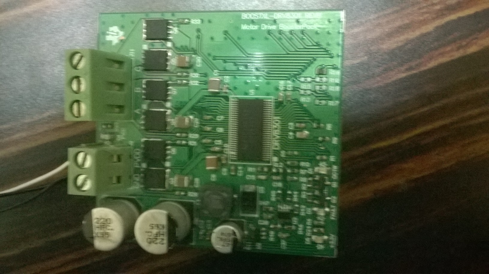
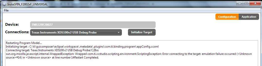
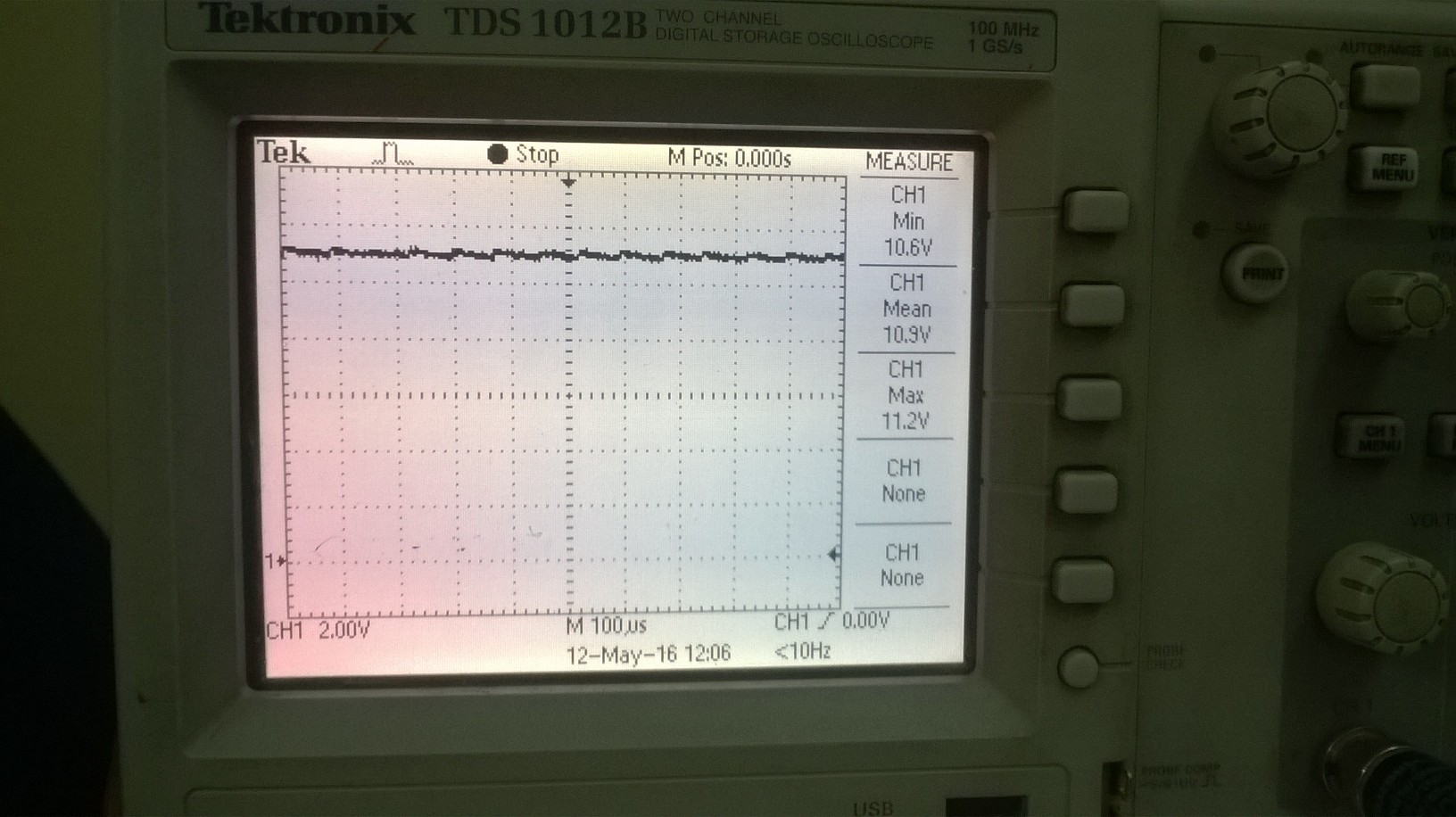
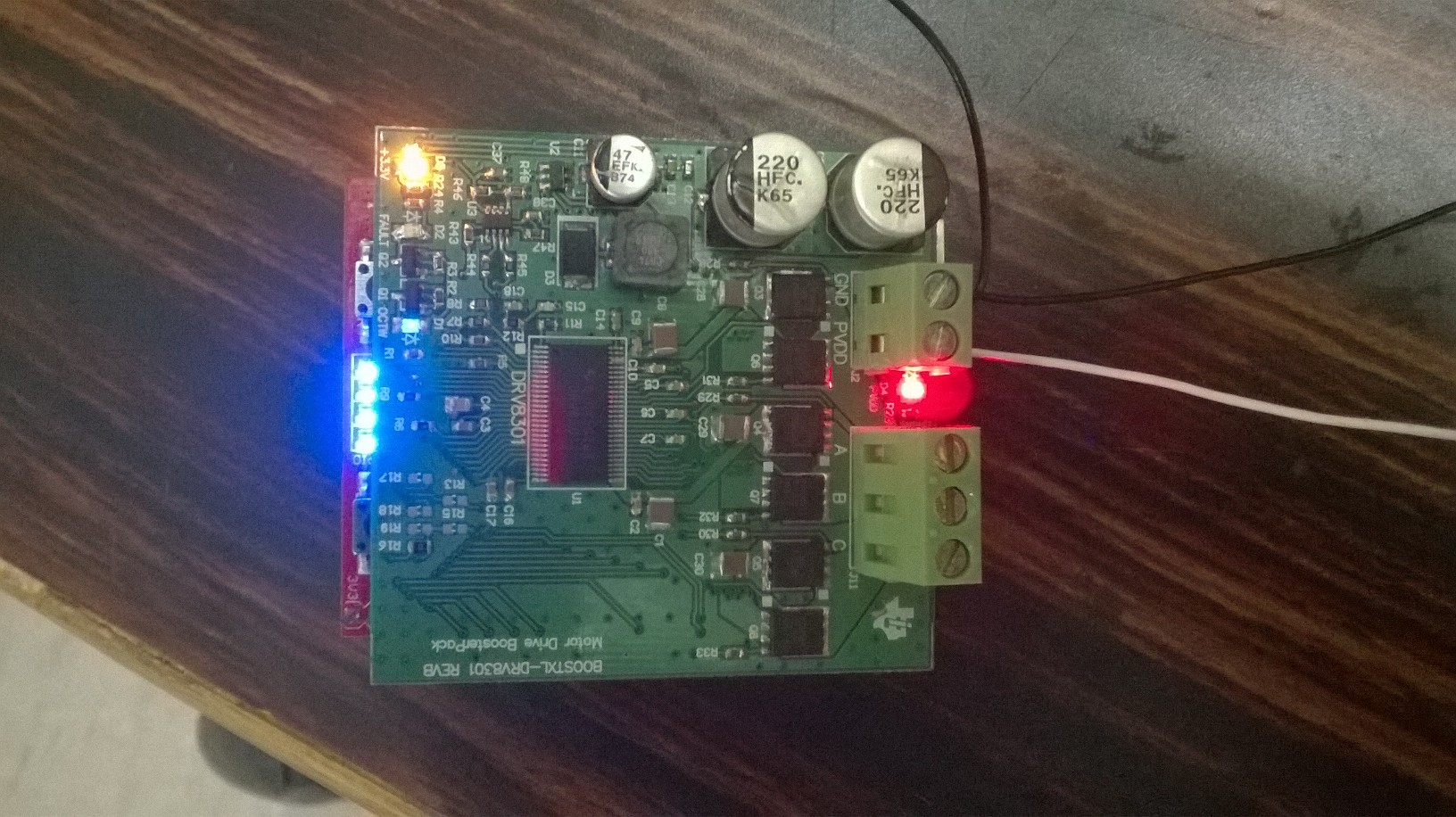
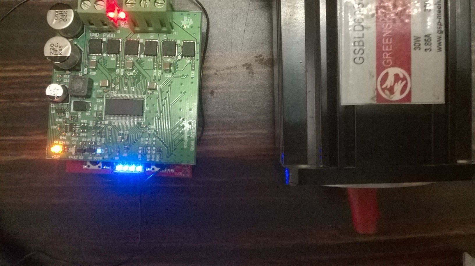
Respected sir, Few days back I have bought a BOOSTXL-DRV8301 insta spin bldc motor driver and as i wanted to manufacture separately the drv8301 driver board, I tried to do that but when I connect the driver board with bought controller board, the gui interface was showing that unknown source and unable to connect. Although the motor has been running with driver board indicating an over load condition, is their any problem with the board or any other issue. For your information the driver board manufactured by me was taken as same as the geber files from texas instrument site. Regards,' Anuroop

  • Hi Anuroop,


    Can you confirm the BOOSTXL-DRV8301 works with the GUI and controller board?
    Can you provide a screen capture of the GUI interface message? If there is a details button, please press it and provide the details also.

    Our expert will be contacted and should reply with more information.
  • Hi,

    What control board are you using? The BOOSTXL-DRV8301 is not compatible with a control board that has InstaSPIN-BLDC. It just supports the launchxl-f28027f and launchxl-f28069m.

    What do you mean by overload condition? How is the driver board indicating this?

  • Respected Sir,

                             I'm using boostxl drv8031 and  launchxl-f28027f . Below link shows the exact kit .

    Regards,

    Anuroop


  • Hi Anuroop,

    As Rick mentioned does the BOOSTXL-DRV8301 still work with the controller?

    Can you power up your board with out the controller and look at the device regulators (DVDD, GVDD, AVDD) and buck output? You can also do some simple input to output testing.

    The number 1 assembly issue for this device is not soldering the PowerPAD to PCB ground. Please check this. The DRV8301 makes an electrical ground connection through the PowerPAD.

  • Respected Sir,

                               Below shown Fig 1, iFig 2, Fig3 are BOOSTXL-DRV8301 purchased kit,  launchxl-f28027f purchased kit  and  Locally manufactured BOOSTXL-DRV8301 board.

                                                                                                                                                              Fig 1. BOOSTXL-DRV8301 Purchased kit                                                                                                                                              Fig 2. launchxl-f28027f purchased kit 


                                    Fig 3. Locally Manufactured BOOSTXL-DRV8301 board


    When I power up the BOOSTXL-DRV8301 purchased kit and  launchxl-f28027f purchased kit  ( Fig 1 and Fig 2) the BLDC  motor is running perfectly and GUI interface working fine.

    But when I tried connect Locally Manufactured BOOSTXL-DRV8301 board and   launchxl-f28027f purchased kit  ( Fig 2 and Fig 3) the voltage at OCTW PIN of DRV8301 is 0V ( as it is open drain it is indicating over temparature or over current ) , as the DRV8301 IC was not heated up it is obviously over current condition and the OC_AdJ_Set register has a value equal to 0x21 ( ie., VDS limit = 0.730V ).  

    Here the BLDC motor was running but when I tried to interface it to gui, below are the errors I faced


    Fig 4 GUI Error Message


    Fig 5 GUI ERROR details

                                                                                                                                                                              Fig 6. operating parameters details.

    The voltage at DVDD, GVDD, AVDD are as follows

    DVDD = 3.3V

    GVDD =  10.6V to 11.2V

    AVDD =  6.48 to 6.72V

    And below are the images without Motor and with Motor load.


    Fig 7 DVDD with out Motor Load                                                                                                                    Fig 8 AVDD without Motor load


    Fig 9 GVDD with out Motor Load                                                                                                         Fig 10 GVDD ripple without Motor load

    Fig 11 GVDD ripple frequency without Motor load


                                                     Fig 12 DVDD with Motor Load                                                                                                                    Fig13 AVDD with Motor load


    Fig 14 GVDD with Motor Load                                                                                                         Fig 15 GVDD ripple Frequency with Motor load


                                                  Fig 16 GVDD ripple with Motor load

    Below are the PCB Images when I powered up the board ( Fig 2 and Fig 3 Integrated )


    Fig 17 Unit with out Motor load and OCTW LED is glowing


                                   Fig 18 Unit with Motor load and OCTW LED is glowing                                                                      Fig 19 Unit with Motor load and OCTW LED is glowing

    Note:

    Green Colour BOOSTXL DRV8301 is Locally manufactured, but the below Red Color is launchxl-f28027f purchased kit 


    Regards,

    Anuroop