This thread has been locked.

If you have a related question, please click the "Ask a related question" button in the top right corner. The newly created question will be automatically linked to this question.

DRV8308 Mysterious Short

Other Parts Discussed in Thread: DRV8308

Hi,

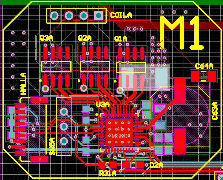
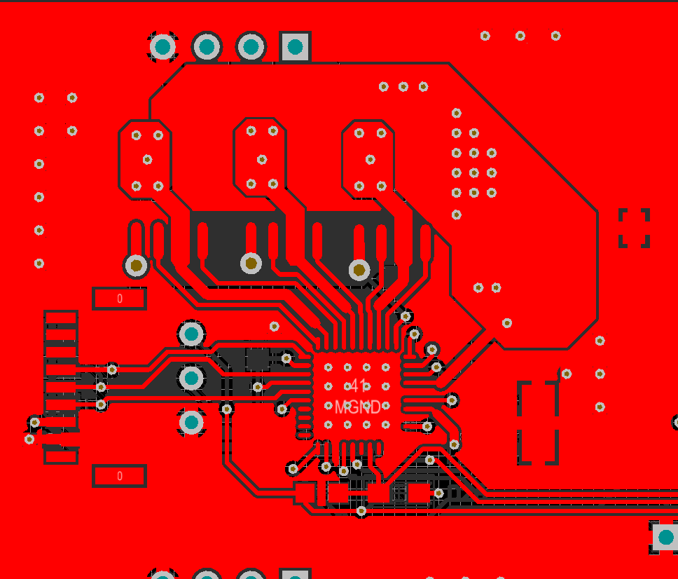
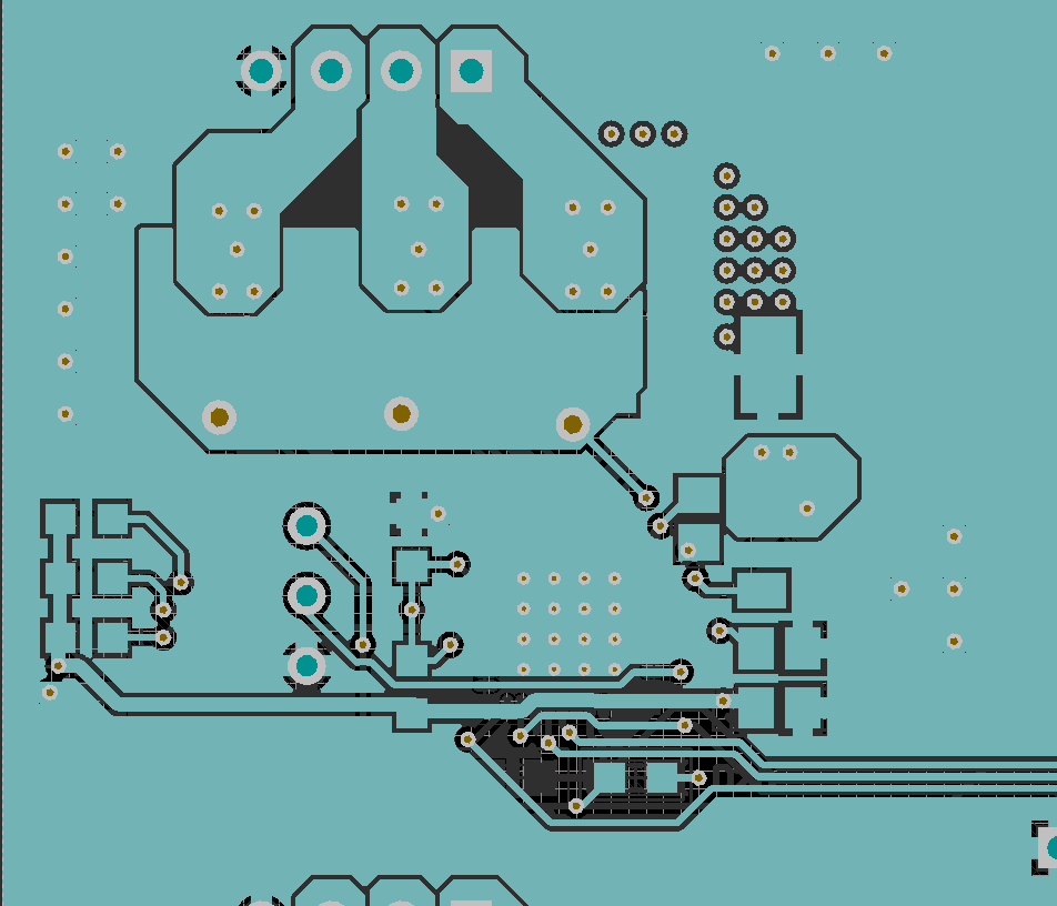
I am using the DRV8308 to control some sensored brushless DC motors.  I have followed the application schematic in the datasheet closely.  Here is my schematic from my board.

MotorController.PDF

I have printed this board and assembled the motor controller portion of it.  When I test for shorts I get a short from VCC_MOT to MGND.  When I remove the current sense resistor the short goes away.  It is not a caused by a solder bridge.  I have tested the MOSFETs and it doesn't seem like any of them are shorted.  The only way I can see this happening is it the high and low sides of the bridges were open at the same time.

The motor was not plugged in for these tests.  They are very expensive and I don't want to risk hurting them until I know the driver is safe.

Can someone tell me what is wrong with this schematic?

  • Hi Jon,

    It could be possible that both your High-Side and Low-Side MOSFETs are latched-on from charge deposited on the gate during your testing and assembly. The DRV8308's gate drive is not active while the driver is off, so if you haven't powered on the driver yet the MOSFET gate will still retain any charge originally deposited on it.

    You could try powering on the driver with the ENABLE pin inactive, this will force all the gate-outputs low. If you're worried about damaging your MOSFETs you could perform this test with your power supply current limited at < 100 mA, the DRV8308 will only draw 120 uA in standby mode and should sink any deposited charge from the MOSFET gates.
  • Phil,

    I have used a multimeter to check the state of the MOSFETs when powered off. The high side of the bridge is shorted but the low side is not. There is approximately a 600 Ohm resistance from VCC_MOT to Coil U, and from Coil U to MGND. However, this is a direct short between VCC_MOT and MGND.

    I tried your suggestion for clearing the charge, but it just caused the OCP to trip. I flipped the EN switch to MGND and set OCP to 500mA. I started the power supply at 12V and the OCP tripped immediately.
  • Hi Jon,

    Could you provide a picture of your PCB and the three half-bridges assembled? The "Use rich formatting" button on the bottom right will allow you to insert images.
  • I don't know if you'll get anything from a picture of the physical board, especially because I can only take it with a crappy flip phone camera.  Here are pictures of the PCB in Altium.  The highlighted component is the current sense resistor. 

    Layers with polygons on:

  • I realized while looking at this that my probing was incorrect.  I was testing the wrong pins.  It seems that pins 5,6 and 1 are all directly connected, which means there is a short through both FETs from VCC_MOT directly to MGND.

  • Hi Jon,

    Did you check the Pin 1 designator of the IRF7103 package against your silk pin 1 designator? If the MOSFETs were populated incorrectly then the body diode of each MOSFET in the package would conduct between VCC_MOT and GND. This would also explain why removing the sense resistor opens the short you're seeing.
  • MOSFET on PCB.  Pin 1 designator is definitely matched with silk.  All three look the same.

  • Hi Jon,

    Thanks for the image. I would suggest you try removing each MOSFET package and measuring the VCC_MOT and GND resistance. This will allow you to determine if one of the MOSFETs has been damaged. I would also suggest measuring the VCC_MOT and GND resistance once all of the MOSFETs have been removed to determine if there is a possible board defect on the internal layer in your PCB.