This thread has been locked.

If you have a related question, please click the "Ask a related question" button in the top right corner. The newly created question will be automatically linked to this question.

DRV8711 Register Optimization

Other Parts Discussed in Thread: DRV8711, DRV8711EVM

Hello TI,

I have a couple questions for the motor experts. I have reviewed both the DRV8711 datasheet and Quick Spin Tuning guide pretty thoroughly.

Furthermore I did a good feasibility study with the DRV8711EVM some months back... As reference https://e2e.ti.com/support/applications/motor_drivers/f/38/p/442973/1592060#1592060 

Regarding general Motor Current...

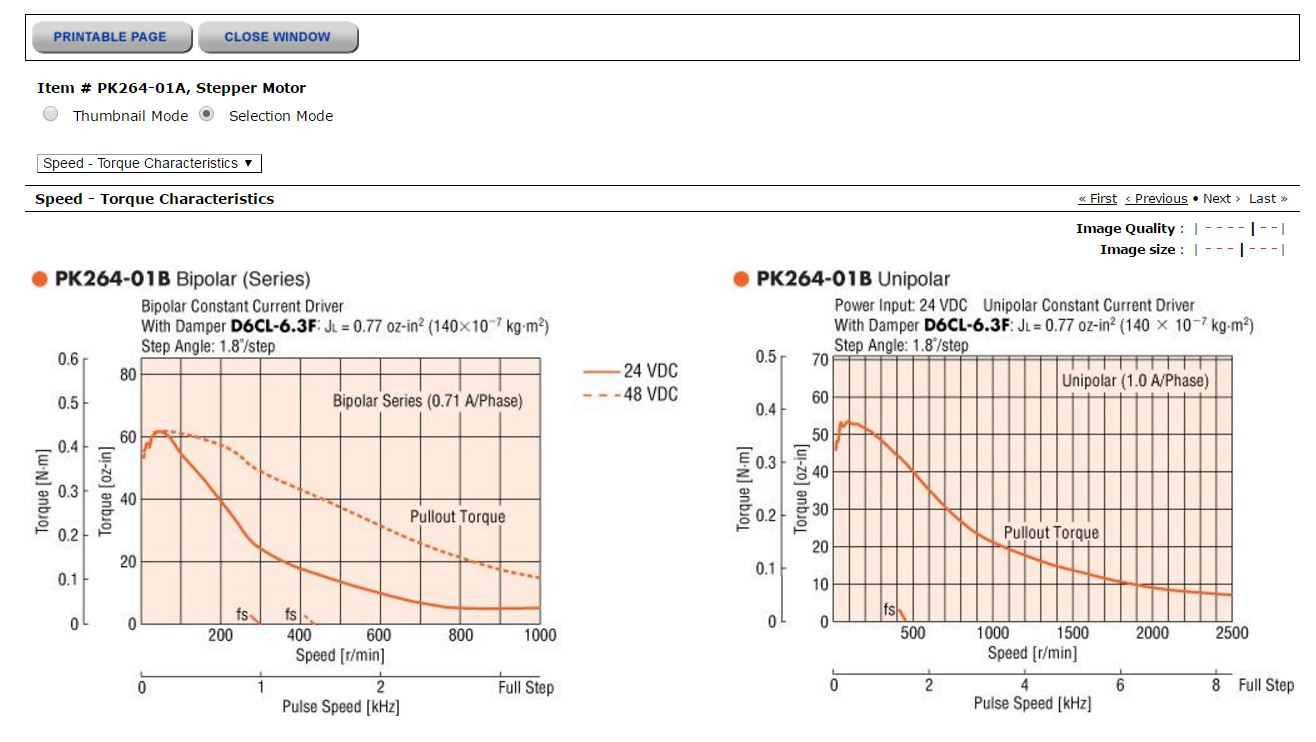
I'm using a PK264 Stepper (datasheet & Torq curve below) with the following specs:
-Current/phase: 1A/phase
-PCB VM: +24V
-Mechanical Load: <= 0.15 Nm
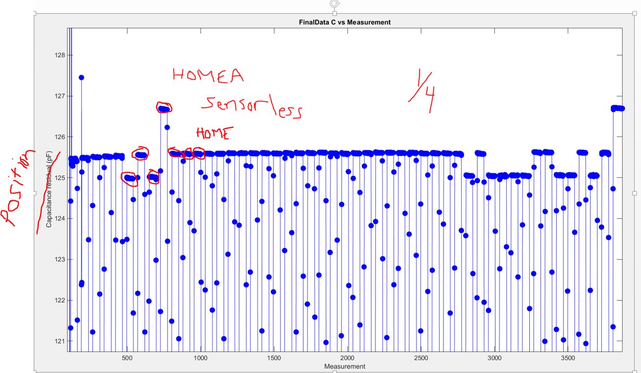
-1/4step Microstepping resolution

1) Since this motor is specified at "1A/phase", what Full-Scale current should I be driving with the DRV8711? 1Apk, 1Apkpk, or something less than 1A?

Regarding Integrated Stall Detection
With the EVM I just wanted to prove I could get it working (which I did, see earlier forum post)... Now I'm trying to optimize for the product.

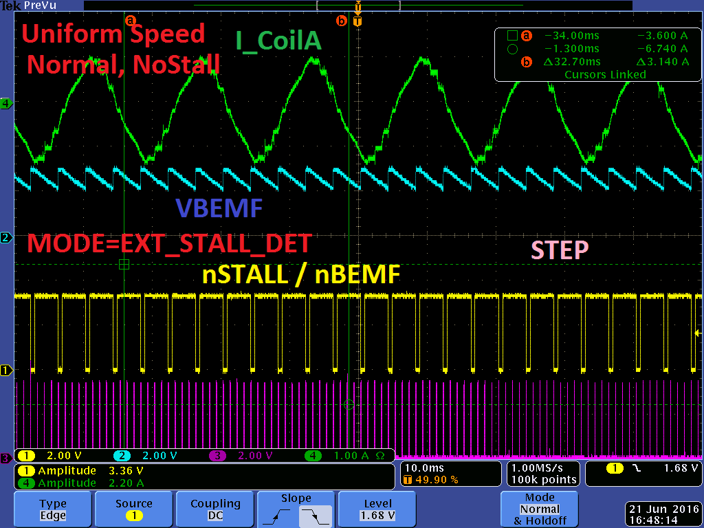
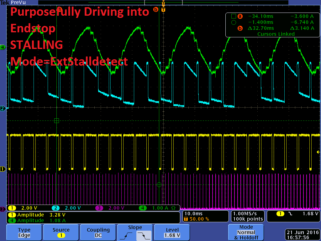
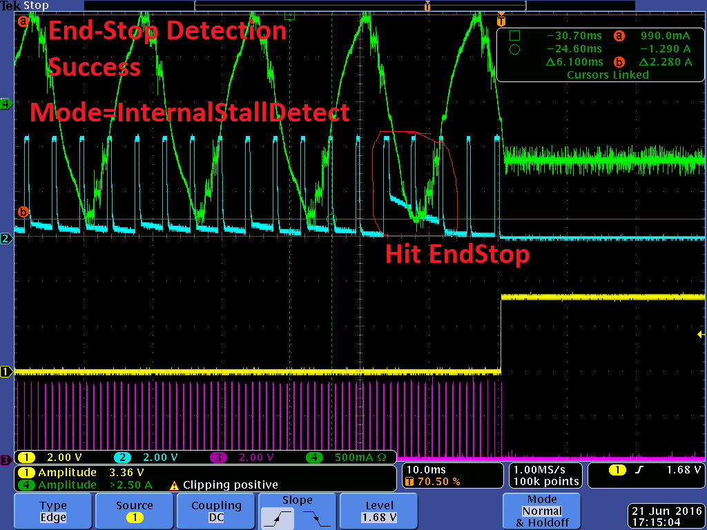
As an application, the goal is to use this feature as an "END-STOP" detection; our motorized system has a mechanical end-stop and I would like to detect this using nSTALL and stop. Hence the goal should be easier than detecting all motor stalls and more obvious BEMF levels (i.e. motion vs no-motion).

2) Can you clarify 'Step Time/Rate' in the statement in the DRV8711 Datasheet says "Step Time, or rate at which step input is applied to DRV8711, has to be greater than SMPLTH".
I can't tell if this means:
        a. Tstep < Tsmplth, hence Fstep > 1/Tsmplth
        b. Tstep > Tsmplth, hence Fstep < 1/Tsmplth

3) The Quick-Spin guide gives no recommendation for SMPLTH, other than the above statement. I have had better/worse success with different values with SMPLTH. Can you explain how I can find a proper value for SMPLTH?


4) In the Quick-Spin guide the recommendation is "Move the motor slowly... Now increase SDTHR or VDIV or both until STALLn becomes asserted... Increasing SDTHR/VDIV will make the stall detect trip at higher speeds.."

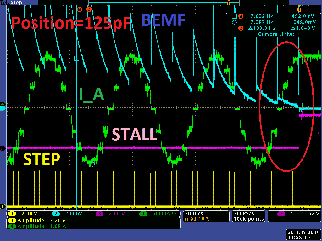
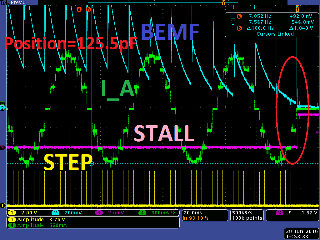
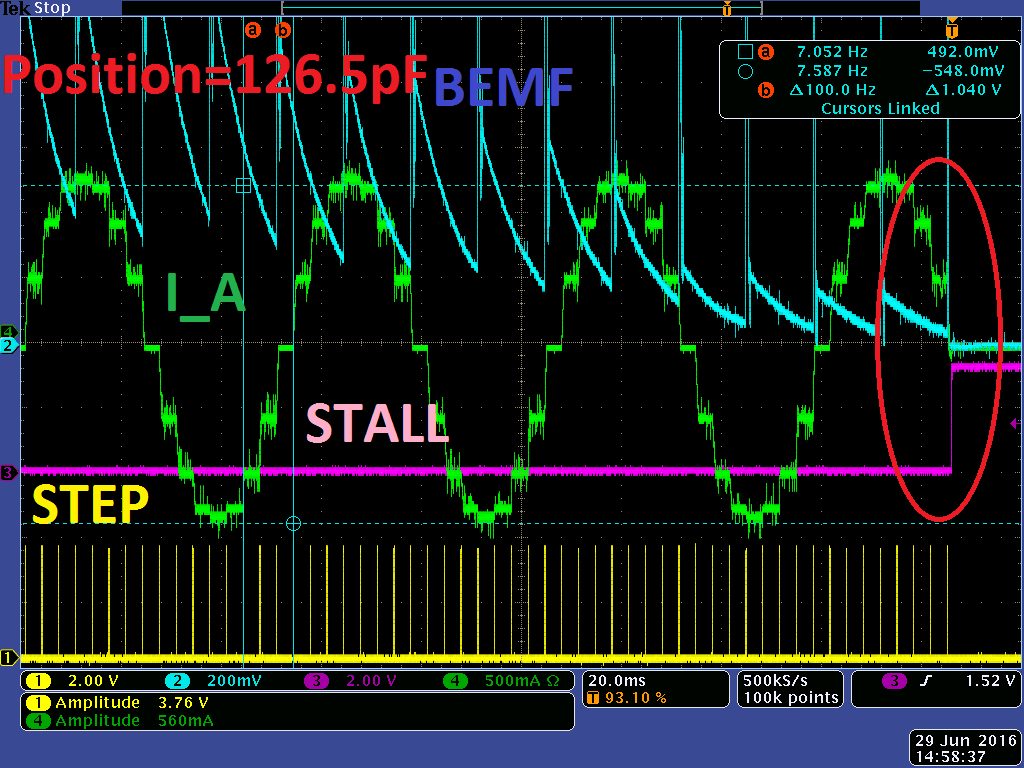
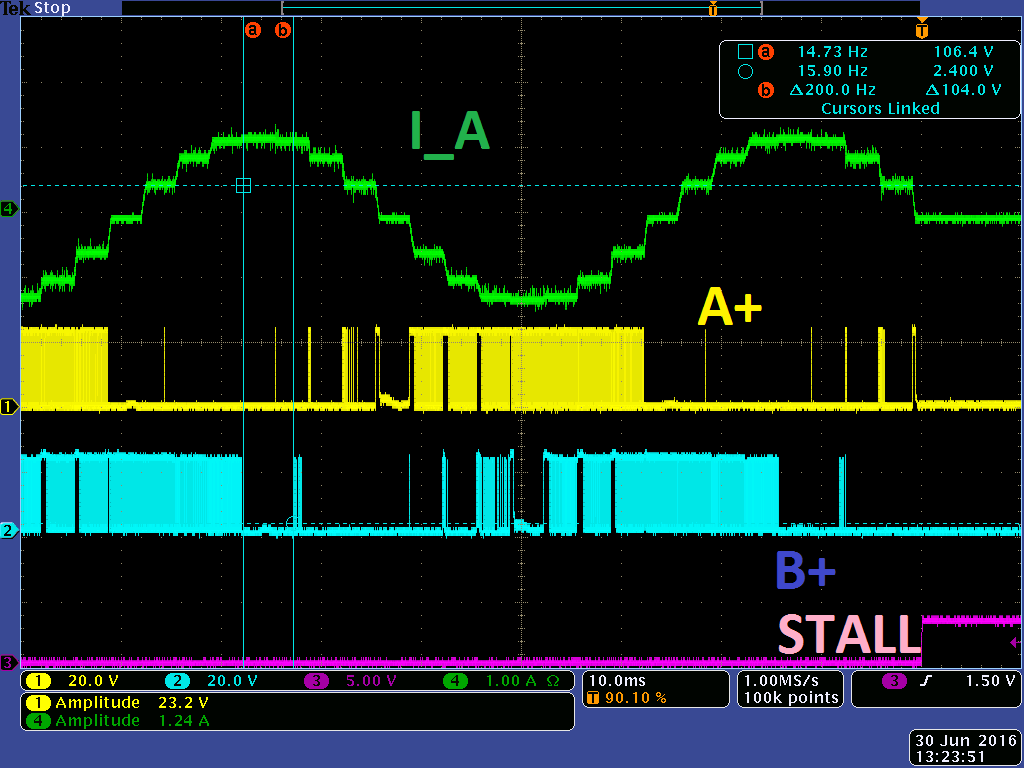
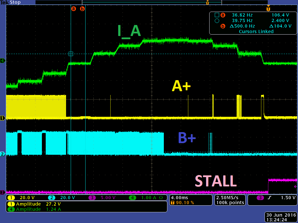
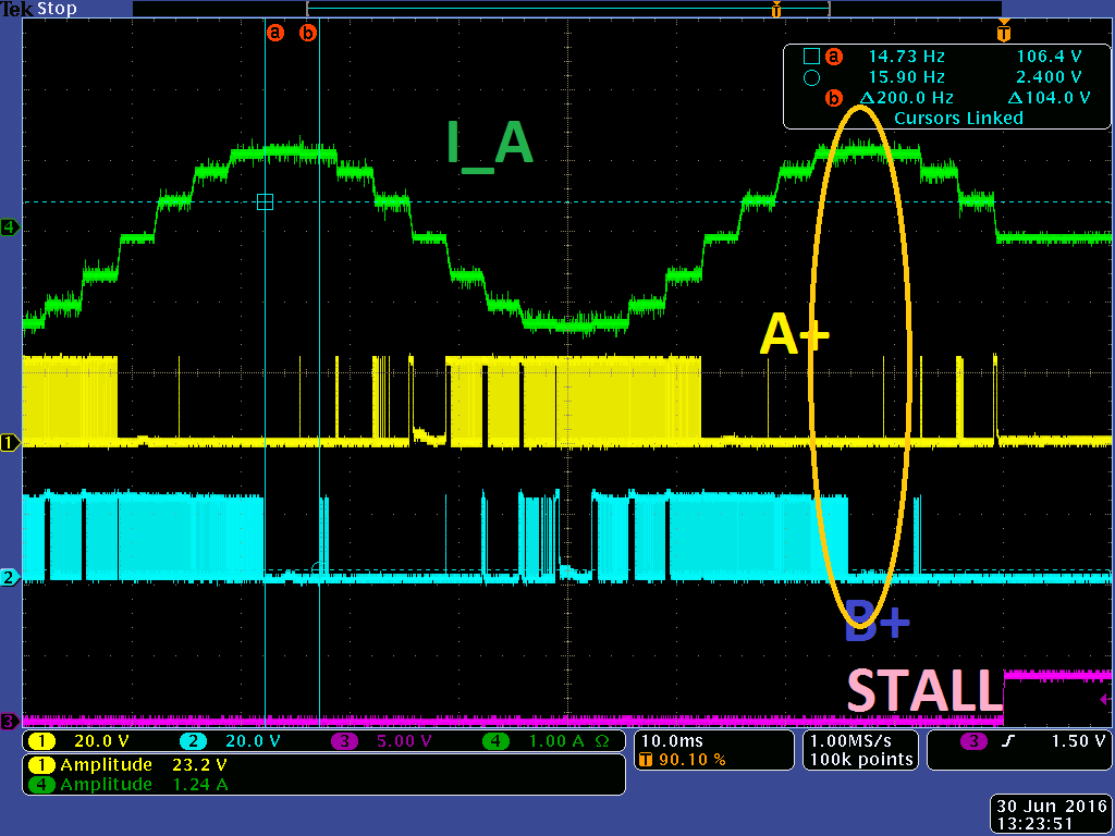
I am having difficulty getting the nSTALL to throw when the motor is moving slowly, even with VDIV=11 (BEMF/4), SDCNT=00 (first step), and SDTHR set to something small like 0x02.
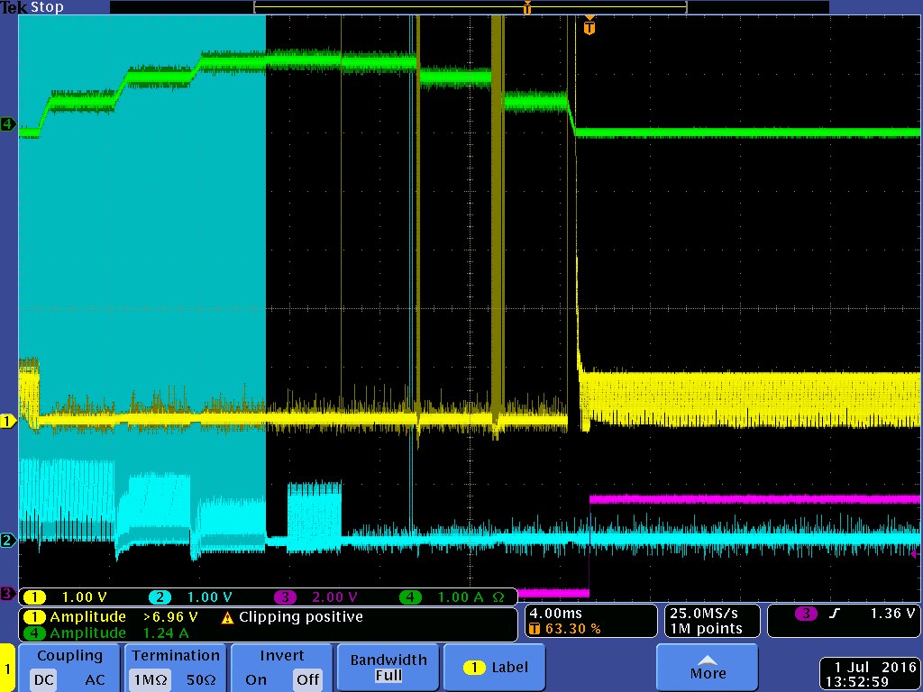
Is there a way I can optimize this by looking at the analog signal in external stall detect mode?


PK264-01A Specification Sheet.pdf

  • Hi, 

    Regarding to the current level question, the motor spec normally give the 1A means the full stepping mode current level. If you are using micro stepping, you can setting 1.4x of that value as the peak level. So the rms level will still be 1A.

    Stall detection parameters could be differenct regarding to the motor parameters and the running conditions such as speed and loading. Have you already get a basic stall detection results? We will get back to you later on your stall questions.

    Best regards,

  • Hi Wilson,

    I've had SOME basic stall detection results... Although my waveforms seem quite different than my waveforms found in my experiments several months ago so I'm concerned something is not working properly... e2e.ti.com/.../1592060
  • Here are some waveforms.

    -A couple different MODES and different CONDITIONS (i.e. STALLING, uniform speed with no stall, INTERNAL_STALL_DETECT vs EXTERNAL_STALL_DETECT, etc.)

    -I've got a Scope Probe on pin 20 VBEMF (BLUE, which explains the drooping of the analog signal after the SAMPLE-HOLD)

    -Microstepping = 1/4

    -Also probably some different VDIV/SMPLTH/SDCNT/SDTHR values as I'm playing with these.

  • Hi Ernie,

    2)  tSTEP = time from 1 rising edge on fSTEP to the next.  If fSTEP = 10 kHz, tSTEP = 100 us.  So, using this time as a base, the SMPLTH register would be best set at 50 us. The SMPLTH register is the amount of time one of the low-side FETs is held on for during the high-impedance state of the H-Bridge.  This value must be less than the STEP time otherwise the Back EMF will not be measured during the STEP interval.

    3)  I would recommend tuning the SMPLTH register to a time interval greater than the settling time at the start of the high impedance step frame.  At the start of a zero-current step there is a settling time until the back EMF is stable.  The SMPLTH register should be tuned to be greater than this settling time.

    4)  You can try reducing the SMPLTH register value to see if that allows more of the back EMF signal to be present in the measurement interval for lower speeds.

  • Hi Phil,

    Can you recommend a way to tune this based on putting the device temporarily in "External Stall Detect Mode" and tuning based on the BEMF signal? I feel like my settings are fairly close to the low-range...

    i.e.

    1) When monitoring VBEMF, what kind of signal ranges should I try to achieve? Is aiming for SDTHR=0x40 reasonable with optimal VDIV and SMPLTH?

    2) Based on your comment above, I can calculate Fstep_max vs SMPLTH. However is there a way I can view the BEMF signal to make sure I'm sampling the BEMF once it's stable?


    FYI the empirical settings I'm currently using and it seems to work most of the time... Except I feel like SDTHR is pretty low... And nSTALL is not toggling during normal operation as I'd expect with low SDTHR setting.

    -1/4 step microstepping
    -Fstep (speed) = 500 Hz, or Tstep=2mS
    -SMPLTH=1mS
    -VDIV = 1/4
    -SDCNT = 0
    -SDTHR = 5
  • Hi TI,

    Can you provide any recommendations for my questions above? Can you guide as to how to optimize the STALL registers while monitoring the analog VBEMF signal?

  • Hi TI,

    I am still hoping for some tips on how to optimize this, preferably by looking at the BEMF signal and tuning for Integrated Stall Detection. My repeatability testing shows that it works decently, but not quite good enough. This project will be a hard sell to move into production quantities without this feature.

    Below is a picture showing my application results repeatedly (i.e. move into hard stop, detect stall, stop, move the other way an offset). The flat peaks represent the stopped "HOME+OFFSET" position, AKA after you've detected a stall (end-stop) move a fixed # of counts the opposite direction and call this "HOME+OFFSET".

    You can see that resolution wise I'm off by a few counts. (I'm PRETTY sure these are 1/4-step Microstep counts, but possibly Full-Steps. It is hard to tell). So I seem to be off by 1-2 counts.

  • Hi,

    The BEMF signal is a sine wave that is clipped at a diode below GND. It is possible to measure a STALL condition when a stall has not occurred depending on the value of the sine wave when sampled. I would recommended setting the SDCNT to max value if you can do so. If that works, you can then back off to 4 or 2 if you get consistent results.

    By the way, the BEMF can be seen by placing a scope on the outputs and observing the voltage during the zero current step. The SMPTH timer is started when the STEP input is accepted.
  • Hi rick,

    Just to confirm what you are saying....

    If I hook a scope up to A+/A- and look at the voltage across the MotorCoil, and look during the Zero-Current step, this is looking at the BEMF?

    I thought this wouldn't work since the driver floats the coil during the Zero-Current step. I was concerned the Scope impedance would pull the signal low.


    Based on the Magnitude I see of the BEMF, is there a peak-to-peak amplitude I should aim for for good performance? i.e. Amplitude is proportional to speed, so I can find good operating speeds this way.
  • I discovered something which is very advantageous and have a few questions for you.

    1) Is there a way to read out the Indexer position? Or is the only way to know indexer is to RESETn (to get 45-degrees) and use the central brain to count pulses.

    2) I am unable to throw STALL during a CURRENT_most_negative_step, and unsure why. (FYI for pics below, STALLn is passed through an inverter, hence the signal is labeled STALL).

    So here's my setup testing repeatability:

    a. 1/4 step Microstepping. Registers have been configured and always detect a stall as soon as I get to END-STOP

    HOME_SEARCH PROCEDURE

    b. Move towards END-STOP

    c. Once STALL gets thrown, stop STEP immediately. After a short delay, move the opposite direction MOTOR_HOME_OFFSET and call this position the "MOTOR_HOME" position.

    d. In addition, to test repeatability, I would do things like "Move 500steps, HOME-SEARCH, move 501 steps, HOME-SEARCH, move 502 steps, HOME-SEARCH,  .... move 530 steps, HOME-SEARCH" to mimic a "HOME-SEARCH" from a random position.

    However when I cycled this several times (see below), I had a quantization of 3 positions.

    It turns out those 3 positions match up EXACTLY with which part of the current waveform the STALL flag gets thrown! 


    I have cycled this 100 times; why am I unable for STALL to get thrown at the MOST-NEGATIVE-CURRENT-STEP? This means right now I have a positional error of 4 full steps, but I am not toggling STALL on the 3rd (this is why position stops are 125pF, 125.5pF, and 126.5pF. 126pF is missing because STALL will not throw on that part of the current waveform.)


  • Hi Ernest,

    1) Is there a way to read out the Indexer position? Or is the only way to know indexer is to RESETn (to get 45-degrees) and use the central brain to count pulses.

    Unfortunately, there is no way to read the indexer position. As you pointed out, counting pulses from RESETn is required.

    2) I am unable to throw STALL during a CURRENT_most_negative_step, and unsure why. (FYI for pics below, STALLn is passed through an inverter, hence the signal is labeled STALL).

    This is puzzling. You should be able to obtain correct stall information at all four zero current steps. Can you provide a scope capture of both the BEMF of the A and B windings (I am assuming the BEMF is for A) . STEP can be removed since it can be determined by the current. From this, it should provide a clearer picture of what would prevent the stall from activating.

    If possible, please zoom in a little further (10ms or perhaps 5ms).
  • Hi Rick,

    1) The previous waveforms the BEMF trace was DRV8711 pin 20 (pin called "BEMF"). 

    2) "...Can you provide a scope capture of both the BEMF of A and B windings..."

    See below; is this what you wanted to see?  I have put a scope probe on the A+ and B+ windings.... not sure if this is what you wanted... It may be hard to see with all the 24V switching going on from the H-bridges?

    I'm not sure what to look for in these waveforms.

  • Hi Ernest,

    Yes, this is what I wanted. The signal will have to be zoomed, but it appears that the area of interest is in this oval below.

    The I_A current has reached 100%, so the I_B current should be 0%. At 20V/division, it is difficult to determine the BEMF. It appears the stall should have asserted due to B+, but did not.

    Zooming into this area and the comparing it with the A+ BEMF that did assert should help determine why it did not.

  • Hi Rick,

    Okay I think I have screenshots of what you're requesting. I repeated this multiple times, but moving in increments of QTY=4 microsteps (1/4 microstepping). This should guarantee that I hit the end-stop/"STALL" at each of the 4 parts of the current waveform.

    Again for some reason STALL doesn't toggle at 1 of the states. (due to my initial position/indexer, it is now at the I_A=0 on the increasing part of the sine wave).

    Any ideas?


  • Hi Ernest,

    Thanks for the scope captures. On the first of the three images above, do you think the stall should have asserted on the zero cross step? I have highlighted the area that I am referring to below.

    Is the stall count set to 00 (first step with BEMF below threshold)  Is it possible the BEMF is acting unexpectedly when the motor hits the stops the first time?

    Let me pull in a colleague for his thoughts.

  • Hi Rick,

    1) Fair question about ..."do you think the stall should have asserted on the zero cross step?" ... Short answer is I'm not sure...

    All I know is I've re-hit the END-STOP by enough varied distances that guranteed in 1 of the cases I should have triggered STALLn from all quadrature parts of the current Sine-Wave. (e.g. distance=100steps, 101steps, ..., 130 steps. And I always get only 3 of the 4 parts of the sinewave).

    I have been thinking of a way to measure when I hit the end-stop independent of the STALLn signal... (e.g. putting a switch in place of the end-stop... that said I want to get this working with this particular mechanical setup obviously).


    2) Currently the StallCount=00

    I have seen you guys recommending a higher value, but I felt I had better success with 00. The reason is straightforward; I want to shut off ASAP once I hit the end-stop. I don't want to excessively drive into the end-stop and damage the mechanical system.

    I can re-test if I get better repeatability at a higher StallCount, but as I recall it wasn't any better (and consisted of a longer duration of driving into the end-stop; confirmed by my ear-hearing).
  • Hi ErnestHank

    I did some test today and just want to share some basic tuning of stall detection. All included in the following picture.

    So the whole C interval is the zero step. Section A is because of current recirculation. Section B is where we should sampling the BEMF.

    Based on this timing relationship, we should make sure A < SMPLTH < C. But some time when motor is running fast with a high level micro-stepping, C is < 50us the min we can set for SMPLTH. That means it is not possiblely sample the correct BEMF. Also Stepper system is open loop. So if the motor is stalled, but the driver is still driving with the fast speed,  the stall detect is not able to function correctly at this senario.

    When the speed or the micro-stepping are proper. We are able to sample the B section. Then, we can just give proper value of STALL register and VDIV. This gives an internal threshold which compare with the sampled BEMF voltage. If the BEMF is lower, the stall detect will be asserted. I can achieve this result if above conditions are all met. Like in the waveform, the pink like gives the nSTALL when I hold the motor. I just give very small current in total to let me stall the motor more easier.

    Best regards,