This thread has been locked.

If you have a related question, please click the "Ask a related question" button in the top right corner. The newly created question will be automatically linked to this question.

Conducted Emission compliance of design using DRV110.

Other Parts Discussed in Thread: DRV110, UCC28710

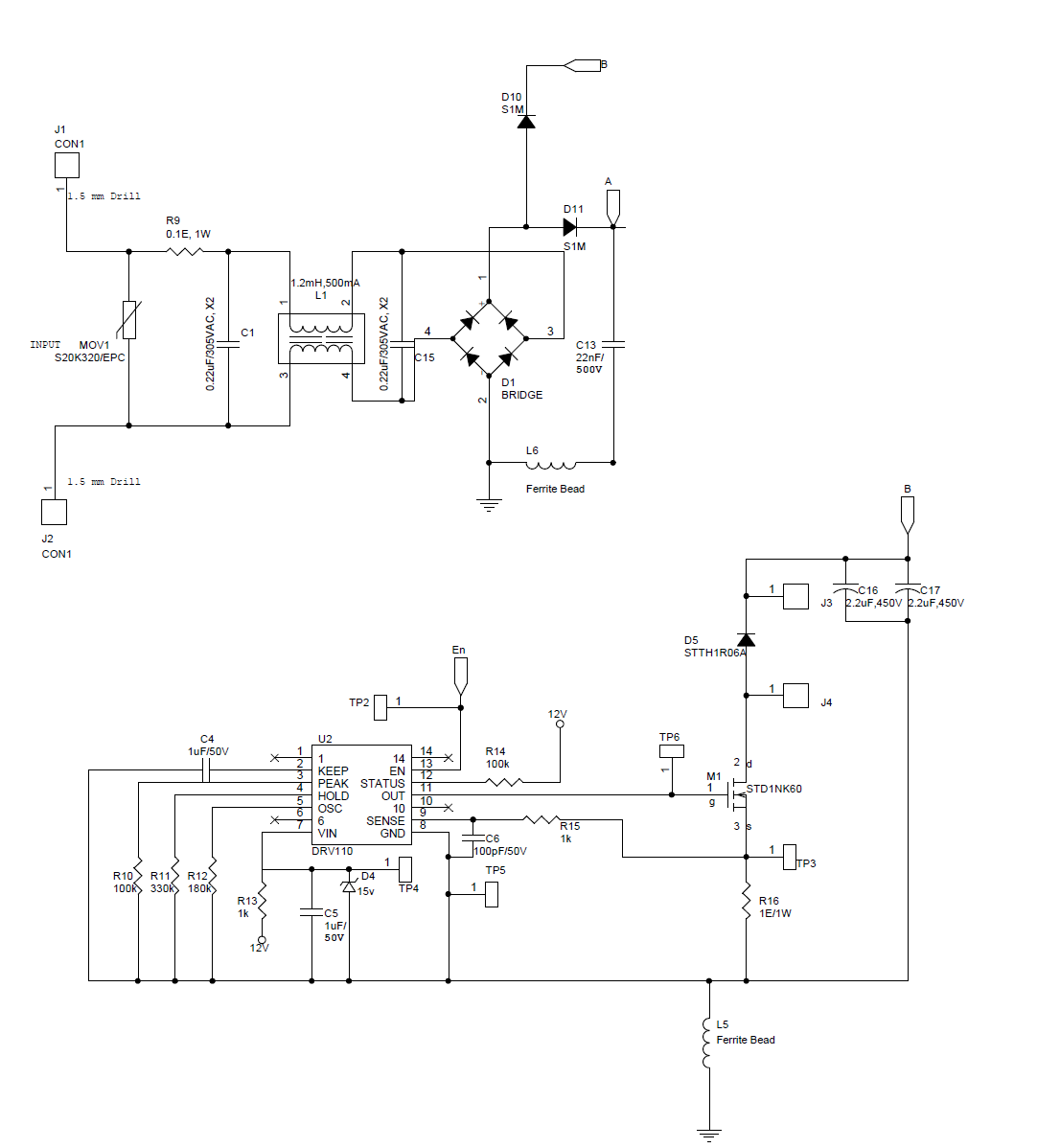
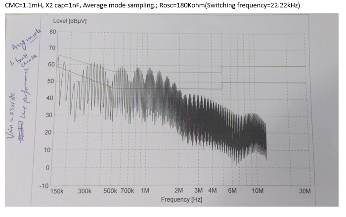
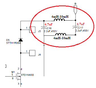
I am using DRV110 in quite a few of my designs to control the operation of a solenoid. The solenoid is being driven directly from bridge rectifier output and is being controlled by DRV110. In one of the designs, the input voltage is 230V, 50Hz. It has become almost impossible to get the design compliant to Conducted Emissions test, unlike other EMI/EMC tests. This design is being powered by UCC28710 at 12V. The configuration is non-isolated buck. The emission from only the SMPS section is almost 34-40dB below limit line. As soon as the solenoid is connected, the emission levels shoot up.

I am attaching snapshots of the circuit and emission levels.

Please provide your inputs on the same.

  • Hi Permankar,

    Our experts will be noticed and get back to you later.

    Best regards,
  • Permankar,

    Thanks for contacting us.

    I have some follow-up questions about your test setup:

    • When you do EMI testing, is your solenoid coil attached between J3 and J4?
    • What is the inductance and series resistance of the coil?
    • Do you observe the EMI frequency content when you power the DRV110 section from a lab supply (disconnecting the SMPS)?
    • Can you please check to make sure you are using your ferrite beads correctly in this circuit? I don't think they should be on the ground connections. Put them on the supply connections - see pages 9 and 10 on this application note:

    As a note, D4 and R13 may be unnecessary. The DRV110 can be powered off of 12 V directly.

  • Dear James,

    Thanks for your inputs.

    Please find my reply to your questions below:

    • When you do EMI testing, is your solenoid coil attached between J3 and J4?: Yes, the solenoid is connected across J3 and J4.
    • What is the inductance and series resistance of the coil?: 663mH at 1kHz, measured using smart tweezers and verified using an LCR meter.(Please refer attached excel for values of the solenoid inductance at other frequencies). Resistance of the coil is 167ohms.
    • Do you observe the EMI frequency content when you power the DRV110 section from a lab supply (disconnecting the SMPS)?: I haven't done this experiment, but in my DRV110 based 415V design, the power supply used is not SMPS, instead is a pass transistor based linear power supply, which does not involve any switching. Even in that design, the Conducted Emission levels are almost the same as the ones I have attached. Thus, I felt that the contribution of SMPS to the CE noise is minimal. Also, as mentioned earlier, the design was tested without the coil connected, and the emission levels were found to be 34-40dB below limit line.
    • Can you please check to make sure you are using your ferrite beads correctly in this circuit? I don't think they should be on the ground connections. Put them on the supply connections - see pages 9 and 10 on this application note: The ferrite beads were put in order to isolate the ground plane. I tried shorting the ferrite beads also but in vain. Anyways, I am going through the application note you mentioned and will take inputs from the same.
    • As a note, D4 and R13 may be unnecessary. The DRV110 can be powered off of 12 V directly.: I agree to your point, maybe I can make the changes later.

    Do let me know if you have further queries.

    Thank You.

    Regards,

    Premankar ChoudhuriInductanceVsFrequency_CE.xlsx

  • Hello Permankar,

    As another reference, please see page 39 of this TI design document. There is a section on conducted emissions.

    www.ti.com/.../tidu578.pdf
  • Hi Ramon,

    Thanks for your input.

    I have gone through the article and have observed that the filter designed requires a physical earth.

    In my design, I do not have a physical earth and it's not also possible to add one. In such a scenario, the filter shown needs to be re-designed.

    Thank You.

    Regards,

    Premankar Choudhuri

  • Permankar,

    Since the conducted emissions test is failing more at a lower frequency (150kHz-1Mhz) could you try increasing the X2 capacitor value and try reducing the switching speed of the FET by connecting a gate resistor between OUT pin and the gate of the FET.

    Would you let us know your observations after doing these 2 steps, please.

    Thank You,
    Ramon Jimenez
  • Hi Ramon,

    Upon increasing the C1 and C15 value to 0.33uF and L1 to around 82mH, there was some improvement in the noise level (the CE test did not pass though). But I cannot use X2 capacitor of value more than 6.8nF as the leakage value of current increases considerably , through the X2 capacitor, when the value of X2 capacitor increases. In such a scenario, the VA specifications of the design cannot be met. Also, the components become very bulky and I have space constraints in my design.

    I had tried adding resistor of value upto 47ohms between OUT pin and the Gate of MOSFET M1, but that made no difference to the CE noise levels.

    I had also tried reducing the DRV110 switching frequency from 22.22kHz to around 5kHz. In such a scenario, the CE test passes for all frequencies, but a shrill audible noise gets generated from the solenoid, which is again unacceptable. I observed that at frequencies below 5.5kHz, the CE test passes.

    Please suggest.

    Thank You.

    Regards,

    Premankar Choudhuri.

  • Premankar, 

    Since you cannot increase the X2 capacitor, can you try increasing the DC bus capacitor and see what changes it provides.

    Also, could you increase C16 and C17. Recommended value is 4.7uF each (this may affect the PF, but the PF may not be an issue, as the power is very small). If this still does not resolve the CE issues add differential inductors in between as shown below.

    Please let us know the results of these changes.

    Thank You,

    Ramon

  • Dear Ramon,

    Thank you for the inputs. I will try the same and get back to you. As I am conducting the test at an external laboratory, I need sometime to update you with my findings.

    Thanks again.

    Regards,

    Premankar Choudhuri.