Because of the holidays, TI E2E™ design support forum responses will be delayed from Dec. 25 through Jan. 2. Thank you for your patience.

This thread has been locked.

If you have a related question, please click the "Ask a related question" button in the top right corner. The newly created question will be automatically linked to this question.

DRV110 PWM Signal - FET not coming fully on every time

Other Parts Discussed in Thread: DRV110

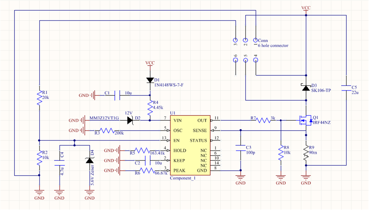
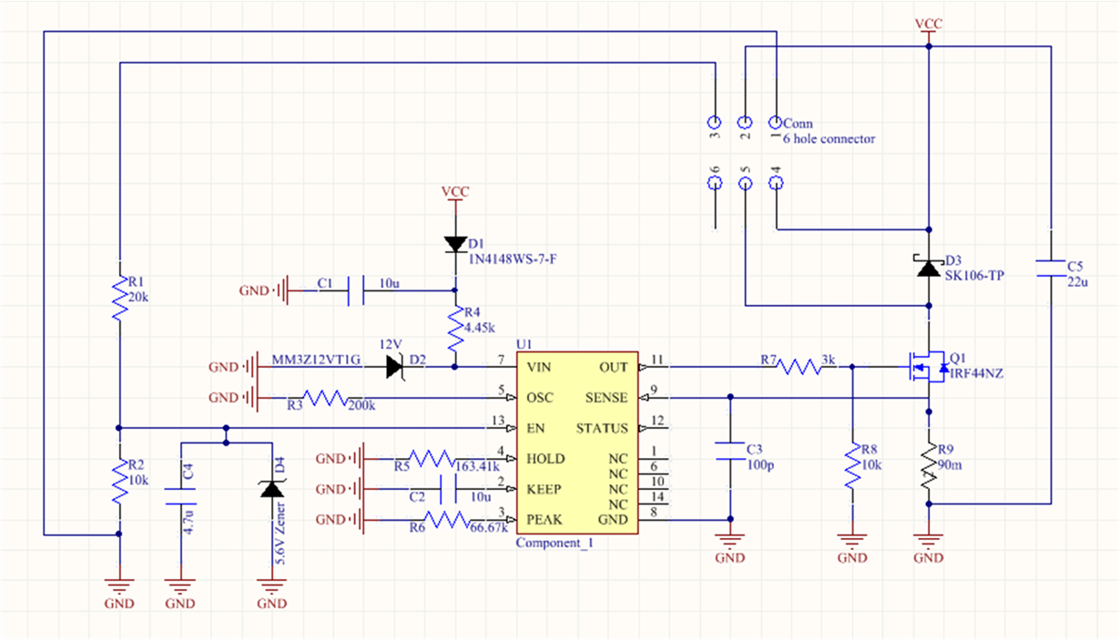
A solenoid driver has been designed using the DRV110 APWR. It is designed to handle a pick current of 10A and a hold current of 0.6A. It is oscillating at 20 kHz and offers a 1s keep time for the pick current. The original schematic can be seen below.


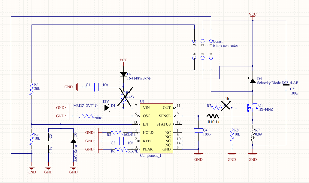
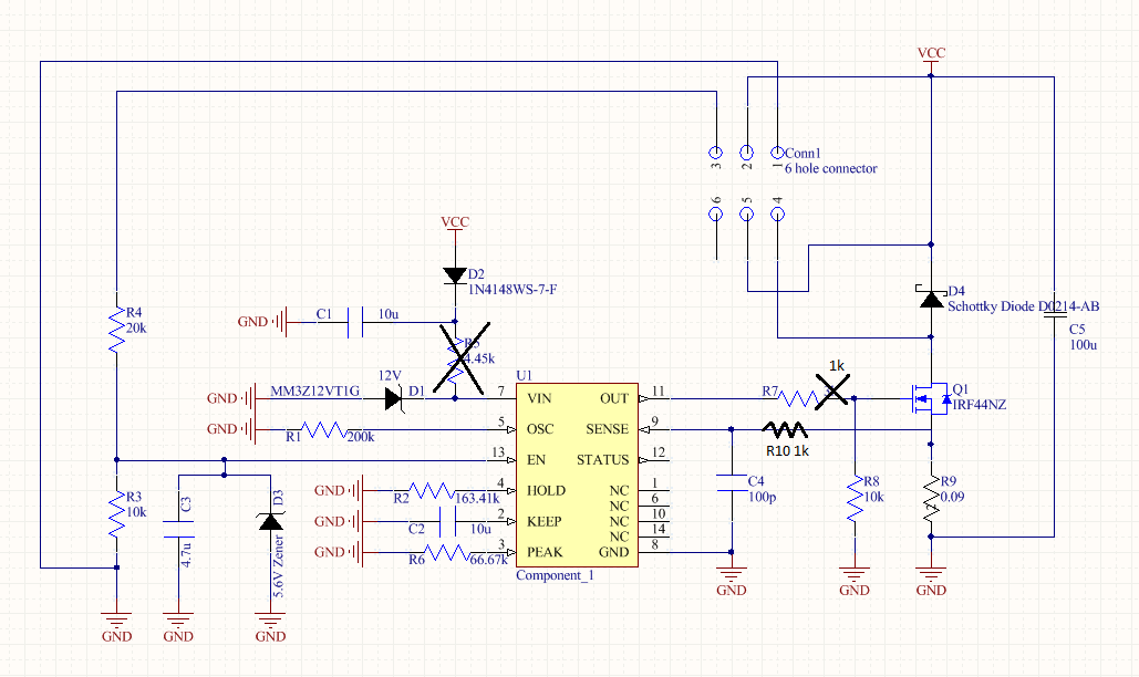
A few edits were made to the original schematic in order to attempt to achieve the appropriate PWM signal. The edits can be seen in the schematic below. A 1k resistor replaced the 3k resistor, an additional 1k resistor was added to the SENSE pin to act as a filter and the 4.45k resistor was removed because it is not necessary at the operating ranges.


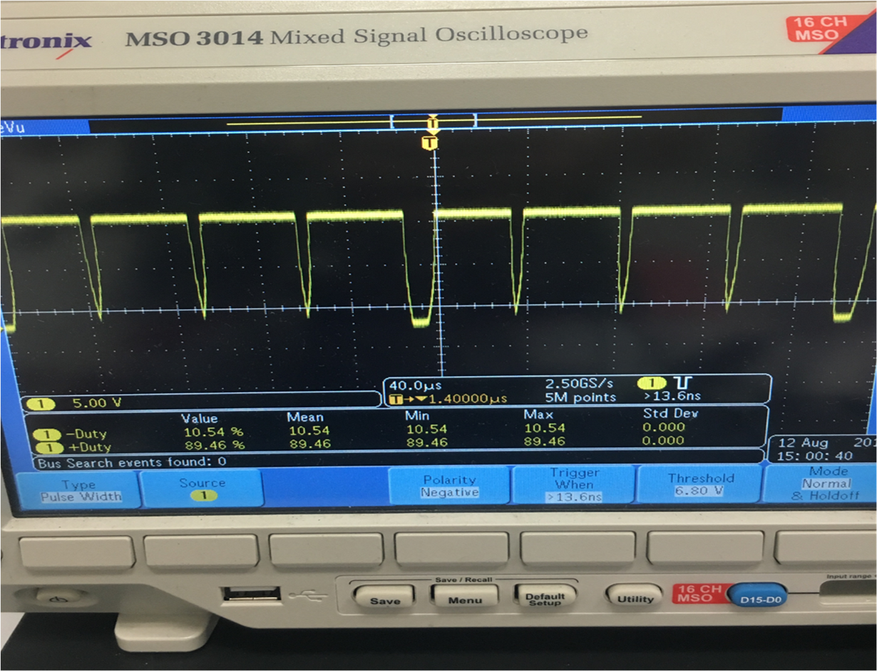
It operates at 12V and is exposed to outdoor temperatures. The oscilloscope of the edited circuit can be seen below. It is being few with a 12V battery at room temperature. The measurement is taken on the output side of the driver and it appears that the PWM signal is not turning on fully all of the time.

The BOM can be seen below in case it is needed.


Identifier:

Manufacturer:

Manufacturer Part #:

Description:

R1

Yageo

RC0603FR-07200KL

200k Resistor 1% [R0603]

R2

Panasonic


ERJ-3EKF1623V

162k Resistor 1% [R0603]

R3

Yageo

RC0603FR-0710KL

10k Resistor 1% 1/10W [R0603]

R4

Yageo

RC0603FR-0720KL

20k Resistor 1% 1/10W [R0603]

R5

Yageo


RC0603FR-074K42L

4.42k Resistor 1% [R0603]

R6

Yageo

RC0603FR-0766K5L

66.5k Resistor 1% 1/10W [R0603]

R7

Yageo

RC0603FR-073KL

3k Resistor 1% 1/10W [R0603]

R8

Yageo

RC0603FR-0710KL

10k Resistor 1% 1/10W [R0603]

R9

Vishay Dale

WSR2R0900FEA

0.09 Ohm Resistor 1% 2W (5*2W for 5s) [R4527]

C1

Murata Electronics

GRM319R61E106KA12D

CER 10uF 25V Rated [C1206]

C2

Murata Electronics

GRM219R60J106KE19D

CER 10uF 6.3V Rated [C0805]

C3

Murata Electronics

GRM21BR61E475KA12L

CER 4.7uF 25V Rated [C0805]

C4

Kemet

C0805C101J5GACTU

CER 100pF 50V Rated [C0805]

C5

Panasonic

EEE-FPV101XAP

CAP 100uF 35V Rated

D1

ON Semi

MM3Z12VT1G

DIODE ZENER 12V 300MW [SOD323]

D2

Fairchild Semi

1N4148WS

DIODE GEN PURP 75V 150MA [SOD323]

D3

ON Semi

MM3Z5V6ST1G

DIODE ZENER 5.6V 200MW [S0D323]

D4

Micro-Commercial-Co

SK106-TP

DIODE SCHOTTKY 60V 10A [D0214AB]

Q1

Infineon

IRFZ44NSTRLPBF

N-CH MOSFET 55V

U1

Texas Instruments

DRV110APWR

DRV110APWR - IC CNTRLR PWM


  • Hi Jordan,

    Our experts have been contacted and should reply soon.
  • Hi Jordan,

    Sorry, but the images did not come through. Please select "Use rich formatting" and try again. You may have to save the image as a file and select either insert/edit media or insert file.

  • Hello Jordan,

    Could you try removing R8 and testing it again, and let us know what the output is.

    Regards,

    Ramon

  • Upon removal of R8, this is the oscilloscope signal from the output side of the driver.

  • Jordan,

    In the scope shots in your original post, what signals are the blue and yellow lines showing?

    Try removing R7 and drive the gate of the FET directly from OUT. I think the slewing you are seeing on the OUT pin may be due to the RC on the gate. If you see ringing on the gate, then add a smaller resistance back (~100 ohm).

  • James,

    In the signal pictures, the yellow represents the output before the filter and the blue represents the output after the filter. I tried removing R7 and directly drove the FET from the OUT pin and it caused the FET to never turn fully on. Replacing them, and changing the from a 100p to a 100n helped me obtain the desired hold current however, the signal is only "good" every other period. Since I am getting the desired current now, I see that as progress. However, I am still unsure as to why the signal is not uniform over every period like is expected

  • Jordan,

    The PWM output will sometimes have a varying PWM signal. The following explanation on page 8 of the datasheet describes this performance.

    "The current control loop regulates, cycle-by-cycle, the solenoid current by sensing voltage at the SENSE pin and controlling the external switching device gate through the OUT pin. During the ON-cycle, the OUT pin voltage is driven and kept high (equal to VIN voltage) allowing current to flow through the external switch as long as the voltage at the SENSE pin is less than VREF. As soon as the voltage at the SENSE pin is above VREF, the OUT pin voltage is immediately driven and kept low until the next ON-cycle is triggered by the internal PWM clock signal. In the beginning of each ON-cycle, the OUT pin voltage is driven and kept high for at least the time determined by the minimum PWM signal duty cycle, DMIN."

    Another explanation I've heard is below.

    "The DRV110 can only sense when the FET is on so it uses the internal clock (aka “PWM generator”) to turn on the FET with the period set by the OSC pin. If it is above the required voltage it turns right back off, otherwise it stays on until it crosses the high side of the hysteresis (which can take many clock periods or not, depending on the inductance). Hence the long on, short on, long on, short on. "

    Try increasing your capacitance or resistance of the filter on the SENSE pin and see if it makes your PWM signal more consistent.