This thread has been locked.

If you have a related question, please click the "Ask a related question" button in the top right corner. The newly created question will be automatically linked to this question.

DRV8823 - Motor not moving

Other Parts Discussed in Thread: DRV8823, DRV8848

Dear experts,

I am planning to use a DRV8823 in my project to drive three DC brushed motors and already have problems get it to run on the breadboard.

Until now I could not get the motor to drive at all.

After reading the datasheet and internet resources and checking my setup over and over I ran out of options and hope to get help here.

The DRV8823 is mounted on a dip48 breakout board connected to an arduino nano on a breadboard.

The PowerPAD heatsink  ist NOT connected to ground and as per the datasheet there is no requirement for that (unlike DRV8848 i.e.).

The schematic is as follows:

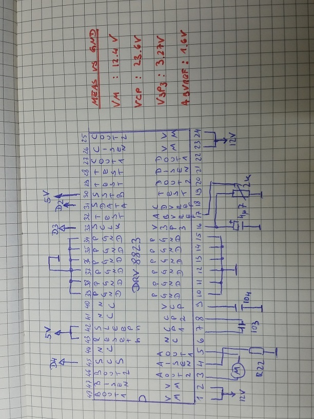
One the right side you can see the relevant voltages as well.

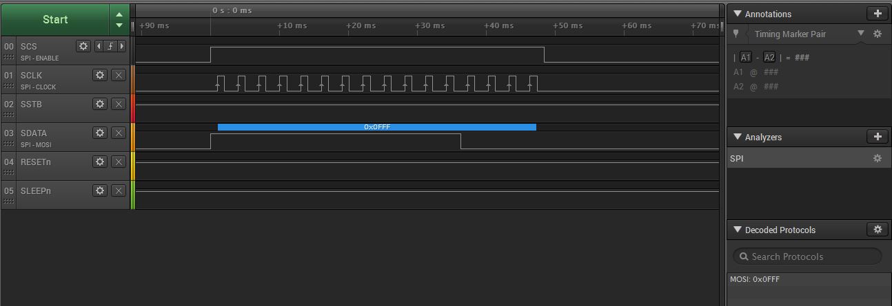
To make sure that all signals are correct I connected a logic analyser and here is the outcome. Note that the protocol decoder is confirming 0xfff being sent.

And last but not least the tiny bit of arduino code in use. For easyness of reading I used bitbanging instead of SPI the interface.

#define DRVCS      4
#define DRVSCK     3
#define DRVSDA     2

void BitBang(uint16_t _send)
{
  digitalWrite(DRVCS, HIGH);
  for(int i=0; i!=16; i++)  
  {
    digitalWrite(DRVSDA, bitRead(_send, i));    
    delay(1);
    digitalWrite(DRVSCK, HIGH);                  
    delay(1);
    digitalWrite(DRVSCK, LOW);                   
    delay(1);
  }
    digitalWrite(DRVSDA, LOW);                  
    digitalWrite(DRVCS, LOW);
}

void setup()
{
  pinMode(DRVCS, OUTPUT);     
  pinMode(DRVSCK, OUTPUT);  
  pinMode(DRVSDA, OUTPUT);  
}

void loop()
{
   delay(1000);
   BitBang(0x0fff);
}

So if anyone has a hint what could be wrong please push me in the right direction.

As per now I assume the chip must be DOA...

Thank you in advance

Juergen

  • Hi Juergen,

    We will investigate and get back to you. It may take a couple of days.
  • Hi Juergen,

    The device is probably good based on the fact VCP and V3P3 are at the proper voltage.

    There are a couple of things to try.
    Have you removed the motor and measured AOUT1 and AOUT2 once the serial transaction has completed?
    If the voltages are correct, could the motor be causing the problem? Is it possible the motor is creating an OCP event? This would disable the outputs.
    If the voltages are incorrect, could there be some noise on the SCLK that is causing the transaction to be mis-interpreted?

    What is the value of R22?
  • Hi Rick,

    thank you for your quick answer.

    R22 ist actually the resistance - 0.22 Ohms. Sorry for not being clear on that.

    Clock signal is in "good shape".

    It's a tiny DC Faulhaber Gearbox Motor. Usually draws ~50 mA @ 12V and it works great on the DRV8848.

    Having it disconnected from the DRV8823 gives me the following:

    AOUT2 vs AOUT1= Crappy sine wave ~ 500mV - I'd say no connection to anything.

    Hmmm - guess I have to get a USB microscope to inspect the soldering on the breakout board.

    Seems to be the only logical failure mode left.

    Regards

    Juergen

  • Hi Juergen,

    Thanks for the clarification on the resistor value.

    Please try sending 0x003f to the device to the device instead of 0x0fff. This will turn on the A output only. If the output enables, I will explain the reason.
  • Hi Rick,

    sorry for the long delay - work is challenging a lot during the vacation season.

    I did try to send 0x003f to the DRV8823 and in deed Aout1 went high to 12V.

    However Aout2 did not go to GND to operate the motor.

    Regards

    Juergen

  • Hi Juergen,

    What voltage did you measure on AOUT2? Have you confirmed continuity to the AOUT2 pin and from AISEN through the resistor to GND?

    When AOUT1 goes high, AOUT2 should go low if the AOUT2 pin. If it does not, there is usually a connection problem or the device may be damaged.

    You can also try sending 0x003d. This should cause AOUT1 to be 0V and AOUT2 to be 12V.
  • Hi Rick,

    Getting closer. Seems that I am fighting inrush overcurrent (with a tiny motor).

    Once the command is sent I hear a very short click.

    So by reducing ABVref voltage and ramping up current regulation (A10,A11,A12)  I can let the motor spin.

    If A10,A11,A12 are set in the first place, inrush current trips OCP.

    Obviously I have to look deeper into current regulation and the current sense resistor.

    Cheers

    Juergen

  • Hi Juergen,

    You should be able to lower ABVREF to 1.3V or change the current regulation to 83%, and start the motor there. Either of these should cause the device to regulate at approximately 1.2A.


    The current limit should not have tripped, but you are very close to the OCP limit of 1.5A.