This thread has been locked.

If you have a related question, please click the "Ask a related question" button in the top right corner. The newly created question will be automatically linked to this question.

DRV110A - is this capable of doing what I need?

Other Parts Discussed in Thread: DRV110, CSD19538Q2, UCC27517, CSD17327Q5A, CSD17507Q5A, CSD17510Q5A, CSD17522Q5A

Hi,

I got an application where I need to replace a relay controlled solenoid with a PWM driven one, to reduce current usage.

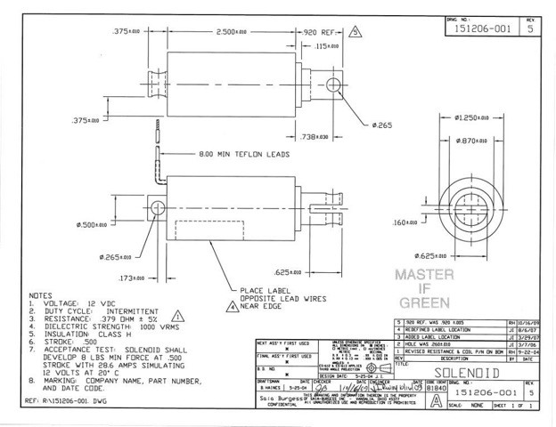
I'm waiting on the customer to give me the specs of the coil. But some real world testing I did, its 12v dc solenoid,

it takes about 10amps to engage the solenoid, yes 10A, to keep it in it needs at least 1 amp

(there is a mechanism that wants to pull it back out). So I would like Ipeak to be 10amps, and Ihold to be 1.5 amps

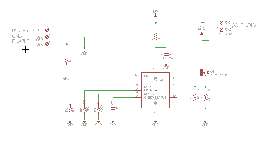
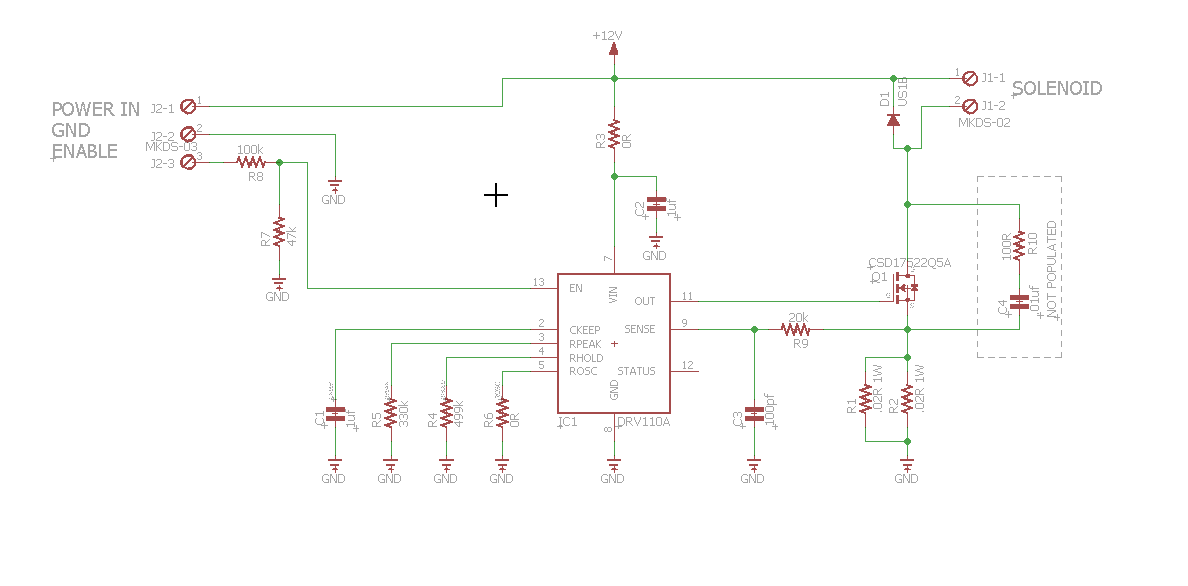
the mosfet I would most likely use is STP16NF06. Can the DRV110A (14 pin version) do this for me?

Thanks and awaiting answer

Mitch

  • Hello Mitch,


    Our experts have been notified and should reply soon. Thank you

  • Hello Mitchell,

    The nominal gate charge for your FET is 10 nC. According to our TI Design documentation, http://www.ti.com/lit/ug/tidu584/tidu584.pdf (page 16), the DRV110 should be able to accommodate this FET.

  • that is great.. so then by saying that, the current requirements of my ipeak/ihold are within the units capabilities?

    do you have anything to aid in calculating the rpeak, rhold , rsense?

    I just found a spreadsheet on this forum..."4265.DRV110 Parameter Selector.xlsx" that helps!

    Q:if the RSense is .03ohm, and 10amps flows though it... dropping 300mv, that's 3watts of power dissipation right?

    Q:can I use a smaller rsense like .01ohm? *field stays green...

    Q:what is a good osc frequency? do I just need to play with it?

  • Mitch,

    1) I believe the current requirements are well within the DRV110's ability. The FET that the DRV110 drives just needs to be sized to handle the voltage and current, which I believe the one you chose does. A FET from out NexFET portfolio, such as the CSD19538Q2, may also fit your needs too (Go here for more NexFET products: http://www.ti.com/nexfet).

    2) The parameter calculator you found is the best way to calculate the required resistances.

    3) Yes, 0.03ohm*(10amps)^2 is a power dissipation of 3 W from the sense resistor.

    4) Yes, you can use an Rsense resistor of 0.01 Ohms. In fact, the calculator shows that you could have a sense resistance as low as 3 mOhm for your settings (Rsens_min).

    5) 20 kHz is a good frequency to use because you can just ground the OSC pin and you don't need to select a resistor. However, you may want it higher or lower depending on the coil's inductance and resistance. Sometimes audible noise can be heard due to the PWM frequency and coil construction. Playing around with it is a good idea. The datasheet shows a max frequency of 25 kHz.
  • thank you so much, I'm going to do a quick PCB layout to allow me to experiment with the solenoid I got here
    before finalizing anything... that's one tiny little fet.. prob not good for my prototype... but final design yes may work!

    thanks again!
  • one thing I just noticed, the EN pin, has a 500k pull up... so when the thing powers up, solenoid will engage..
    id like that not to happen for safety reasons, if my micro resets, the pin could go high... so what is a recommended pull down resistor? (10k? 47k?)
    my micro is 5v logic

    thanks
  • Mitch,

    10 kOhm is a good value I've seen used before.

    The threshold for the EN pin to see a LOW value on the input is 1.3 V. So long as the voltage divider created between the internal pull up and external pull down produces a voltage less than 1.3 V, the DRV110 will see that as a LOW. Here's the formula:

    1.3 > VIN*(350K*R_pulldown)/(350K+R_pulldown)

    I used 350K for the pull up resistor because it's the minimum value for the pull-up resistor in the datasheet. Using 350K is designing for part-to-part variation for the DRV110. If the pull up is 500K, but you design for 350K, then the voltage at the EN pin will be even lower.

  • ok, 1st shot... some success...

    I had to change rPeak to 330k ohms, needed more current for pull in, oh the specs on the coil turns out to be .379 ohms at 12vdc

    but sometimes (> 50% of the time) it pulls in and I can hear the coil making squealing noises, and its is sound is changing... not just high freq
    and current draw is 5 to 11 amps! and if I touch the tab of the mosfet, it changes sound!
    other times it pulls in, I don't hear anything and current draw is .45 amps (10% of the time)

    the mosfet does get hot during hold time...

    any ideas??

    is there a MAX voltage for the EN PIN? (id guess VIN)

  • for sure something is oscillating...

    in the TIDU578 reference schematic, what does R30/C9 do?

    its ok to leave STATUS in connected? or should I connect and pull up?

    THANKS!

  • Mitchell,

    Are you using the STP60NF06 FET in your test board as shown in the schematic? I don't think this transistor will work. The gate charge is 54 nC, and the DRV110 does not have enough drive current to turn that transistor off and on quickly. The transistor is probably hot because a lot of power is dissipated when FETs are switched slowly. Use an oscilloscope to check the signal on the OUT pin and the SENSE pins to see how well the FET is switching.

    If you want to use the STP60NF06, you will need a gate driver between the DRV110 OUT and the FET's gate. I have seen the UCC27517 recommended for this on other systems. Otherwise, try using the first transistor you mentioned (STP16NF06). It has a gate charge of 10 nC, which should be within the DRV110's capability.

    One thing I would also recommend for your design is to add an RC filter on the SENSE pin as shown here (R35 and C10).

  • The maximum voltage on the EN pin is 7 V (see Absolute Maximum Ratings in the DRV110 datasheet).

    I believe R30 and C9 are used to filter higher frequencies from the PWM output. You can include this if you want, but many systems I've seen don't use it.

    The STATUS pin can be left floating or pulled up - either is fine.

  • ok, on the EV voltage, I must have been blind, I did look at absolute section..

    I will add in the filter r/c on the sense line...

    I can try switching to the STP16NF06, which is what I ment to use...
    seems hard to find a mosfet with my current (i want 2x the solenoid needs) needs with a lowe total gate change

    thanks
    ill make some changes and try again

    mitch
  • Mitchell,

    TI has a many FETs in our NexFET portfolio that I think would match your requirements.

    The CSD17327Q5A is a 30-V FET with 2.8 nC gate charge that can handle 65 A of current. We have a MOSFET selection tool that can help you.

    webench.ti.com/.../index.jsp
  • ok.. looking there...
    I been trying to find on mouser, and they don't seem to track all the gate charges, and I end up having to open so many spec sheets
    the thing with the one you recommend is its package!... since I'm only at testing stage I'm hand assembling
    and I don't think that package is in current EAGLE.. ill have to look and maybe modify

    do you know of any TI fets in maybe DPAK or D2PAK?

    thanks again
    mitch
  • Actually, the max VGS voltage of the CSD17327Q5A is too low. The CSD17507Q5A may be a better choice. The gate charge of that device is actually about 9 nC at 15 V, but that should still work for you.

    What is the equipment you are building?

  • You can search for FETs using parameters of gate charge and package size at ti.com/nexfet

    It looks like we have some D2PAK devices, but you would need to use a gate driver with them because of their high gate charge.
  • ok, ill use the CDS17507Q5A... and I lucked out I do have that footprint already made...

    this is to replace a relay controlled solenoid in a wheelchair locking mechanism
    right now the relay is on 3 seconds, and 10+ amps flows putting stress on wires and connectors
    they get warm
    this is to replace the relay...

    mitch
  • how about CSD17510Q5A
    seems to have more current handling, as I feel its between 11 and 15 amps to pull the solenoid in
  • I hesitate to recommend that one. If you look at the graph on the first page, the gate charge will actually be 15 nC for a VGS of 12 V and the DRV110's gate drive is lower at 12 V (spec sheet gives it at 15 V). It may work, but switching will be slower.

    If you have more questions about our NexFET portfolio, I recommend posting in the NexFET forum. I've included a link below. They should be able to help you with part selection based on your system requirements and the DRV110's gate drive capacity. They may also be able to provide you with Eagle footprints for their parts, but I'm not sure about that.

    e2e.ti.com/.../208
  • ok. will do... learning as I go with mosfets
    (I'm a software guy who dabbles in this stuff)

    I'm going with CSD17522Q5A for now... just to get the thing working!
    shows gate charge at a little over 8nc at 12vgs

    thanks
    mitch
  • James,

    a Step forward and a Step backwards

    this just doesn't work right...

    here is current schematic...

    When assembled like this, and 12v put on enable, the solenoid chatters... (as it cant pull in)
    with assistance, I push it in, and it stays in... so keep is working
    during this time there is no oscillation noises, mosfet is cool, but the DIODE does get a bit hot.. nothing to make me take finger off it... but it does get hot
    (which seems odd to me)

    now if I remove the sense filter cap, C3, the thing pulls in and stays in...
    BUT there is oscillation noises from the solenoid, and the MOSTFET GETS REALLY hot, fast!!
    (so I dare not risk keeping engaged for more than a second or two)

    any thoughts?

    so close, but so far...

    Mitch

  • ok, I lowered r9 from 20k to 1k, as I see it in the EVAL board
    works MUCH better, still chatters as it pulls in the solenoid, but it gets in 90% of the time
    D1 still gets HOT during the time is in, its a 100v 1a fast acting diode...

    closer maybe...

    mitch
  • update

    it seems I got some stability, when I lowered RPEAK resistor, to 220k
    which is like 27amps

    now the diode still gets hot...

    but no more oscillation, and solenoid pulls in right away

    I finally found some info on the coil, its .379 ohms at 12v
    to me that's 31+ amps!

    now, in the ipeak formula.. where does the 900ma come from
    I'm really confused how to calculate Rpeak

    Rpeak = (900 * 66.67) / (Rsense * iPeak)
    Rpeak = (900 * 66.67) / (.01 * 18)
    Rpeak = 333 ohms

    that right? for 18 amps?
    where does that 900 come from?

    I read this 1000 times, and it still confuses

    For example, if a
    50-kΩ (= RPEAK) resistor is connected between PEAK and GND, and RSENSE = 1 Ω, then the externally set
    IPEAK level is 900 mA. If RPEAK = 200 kΩ and RSENSE = 1 Ω, then the externally set IPEAK level is 300 mA. In
    case RSENSE = 2 Ω instead of 1 Ω, then IPEAK = 450 mA (when RPEAK = 50 kΩ) and IPEAK = 150 mA (when
    RPEAK = 200 kΩ).

    mitch
  • Mitchell,

    Can you please send me the datasheet of the solenoid? What is the inductance?

    Also, can you please send me the datasheet of the diode? If the current you are regulating through the coil at peak is 18 amps, then that means 18 amps will flow through the diode when the FET turns off. If your diode is only rated for 1 A, it could fail or not last very long.

    The best way to troubleshoot the DRV110 is with an oscilloscope - it saves burnt fingers :-). I usually probe the OUT and SENSE pins when I'm troubleshooting. Also, if you have a current probe to check the current through the solenoid, that is very helpful too. Can you please send some scope shots for me to review?

    For your question about the PEAK current calculation, the 900 mA value is some constant that comes from the way the internal reference is configured. It is a scaling factor to differentiate it from the HOLD current when default values are used. The equation is only valid for resistors from 66K to 2M. Resistors below 66K will have different defaults. Figure 3 on Page 9 of the datasheet is a graph that shows what the current will be for resistor values 0-250K.

    James
  • james,

    what I got on the solenoid is extremely limited, I asked for a full datasheet and got this...
    I think the peak of this solenoid is higher than 18amps...
    the diode only heats when its in HOLD and there is only .22amps flowing

    the diode into: http://www.mouser.com/ProductDetail/Diodes-Incorporated/US1B-13-F/?qs=sGAEpiMZZMtbRapU8LlZD6KDHQne%252bIW0QanGX6gpb2Q%3d

    I got stability in the circuit now, when the RPEAK is 220k

    Ill work on setting up scope if needs be, but it looks like I'm down to solving this diode thing...

    mitch

  • Mitchell,

    Without scope shots, it's hard to determine why the diode is heating.

    However, I do have a guess. Are you measuring the 0.22 A with a digital multimeter? If so, then that is showing an average current. If the current regulated through the coil during HOLD is 2 A, then that means the duty cycle of the PWM signal in the HOLD state is 11%. That means an average current of 1.78 A is flowing through the diode (which is out of spec from the datasheet). The forward voltage drop is 1.3 V. The power dissipated by the diode will be 1.3*1.78 = 2.314 W. Using the thermal junction impedance in the datasheet, 30 celcius/W, I calculate that you diode will have a temperature rise of 69 celcius. Adding room temperature to that (25 C), the temperature of the diode will be 94 C.

    One thing you can do is regulate at a lower hold current. Have you tried a hold current of 1 A or less?

  • interesting idea... and makes some sense to me..
    I did a quick test, changed RHOLD from 500k to 1meg, to set IHold to 1Amp

    Still gets hot...
    I got a 2 amp diode on the way.. should be here in a day or so
    I then can also set up scope...

    got this diode... its vf is 1.7 so if current is same 1.78a... the power dissipation is 3w
    says 25c/w... so that's 75c + room temp... that's hotter? (am I doing this right)
    now at the lower IHold (1amp)...

    http://www.mouser.com/Search/ProductDetail.aspx?R=STTH2R06Uvirtualkey51120000virtualkey511-STTH2R06U


  • Yes, your understanding is correct, and the diode will be hotter. However, you are operating it within the datasheet specs, and your new diode can withstand a higher junction temperature, so I imagine it will be more reliable in your system.

    To reduce the current recirculating through the diode, you might be able to vary the ON time of the PWM signal. If you can keep the FET on longer, than the average current through the diode will be less. I think you might be able to do this by increasing the sense resistance or decreasing the supply voltage. Although decreasing the supply voltage might be difficult if you're using a fixed battery voltage. Of course, this is all speculation until you can take scope shots to determine if my assumption is correct, and that this isn't related to something else.

    Another thing you can try is to put two diodes in parallel. This will reduce the heat produced by each diode, but I think your total thermal dissipation will remain the same.

    It's just the nature of electronics components that use large currents, something is going to heat up. If you can still leave your finger on the FET, then it's not going to be too hot to cause a failure.

    What is the temperature range over which your system needs to be guaranteed to operate? How many units of this system are you planning to manufacture (you can answer this in a private message if you don't want to post it on the public forum)?
  • ok, got the new diode, as predicted it gets hot, the old finger test is 6 seconds... I measured with IR temp meter, and its 97F

    the FET to me while next to the diode is cool as can be

    my operating conditions vary in temp so much, its a automotive, It could be high as 50c... but the good news is
    normal operation is solenoid only engaged for 5 seconds

    the idea of two in parallel is prob way to go... then each dissipates 1/2 the wattage

    mitch