This thread has been locked.

If you have a related question, please click the "Ask a related question" button in the top right corner. The newly created question will be automatically linked to this question.

Blown DRV 8801

Other Parts Discussed in Thread: DRV8801, DRV8841, DRV8842

Hello,

I have a circuit using two DRV8841 and one DRV8801 fed by a 24V 10A chinese DC switching power supply. I have one 4A DC Motor connected to each DRV8841, 8801 is unused at the moment. The DRV8801 blew up (no load connected), and I have no Idea how this could happen. Now the DRV8841s are also not working anymore. It happened while driving the big motors with the 8842 drivers. 

In what case such a damage of the chip can happen? Do you have any suggestion what to check?

Thank you,

Igor

  • Hi Igor,

    Damage of this type is usually caused by some type of electrical overstress. A common cause is a voltage spike on VM.

    Have you measured the resistance of this board from VBB to GND, outputs to VBB and GND, and all other pins to VBB and GND? Do you see a difference between a good board and this board?

    Can you remove the DRV8801 to determine if the DRV8841s begin operating again?

    What is your bulk capacitor value on your board? Have you looked for voltage spikes on VM/VBB while the DRV8841s are operating? If the voltage spike is too high, it could damage the DRV8801.
  • Hello Friend,

    I have measured the voltage while driving one motor, the power supply dripped from 24 to 18V for 20ms and then rised up again. I did not measure driving both motors.

    I had much lower resistance in this board from 8801 output to VBB and GND. I removed the 8801.

    Now I have short from 8841 Output 1 to GND (0 Ohm). This is not so on the good board, >2M resistance here.

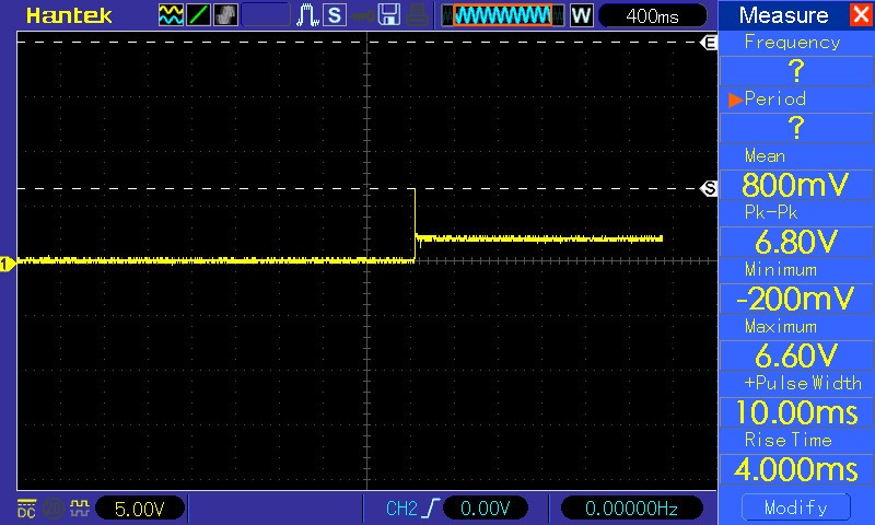
    I removed the 8801 - but the board is not operating again. Here is what I see with a scope on the 8842 outputs (both chips are the same:)

    This 50Hz are strangely accurate. I checked the supply, and it is not oscillating. IC has no load here.

    Bulk capacitance is 100µF. Is this appropriate? 

    I have not measured the voltage peaks on the outputs while driving the motors.

    I have tested the board long time with 2x12V batteries in series and it worked well. Problems started when I changed to the 10A Switching Supply, do you think this could be causality or can be the source of the problem?

    Thank you,

    Igor

  • Hi Igor,

    I have seen this when a scope probe ground was not working properly. Can you check your scope probe?
  • Hi Rick,

    You where right, I was measuring OUT1 to OUT2. Now I measured them to GND and I see practically no output.

    Here is what I measured: (IN2 was LOW)

    CH1 IN1

    CH2 OUT1

    CH1: IN1
    CH2: OUT2

    CH1 IN1
    CH2 FAULT

    CH1 IN1
    CH2 nSleep

    CH1 IN1
    CH2 VCP (PIN3)

    What do you think?

    I am driving this motors with the 8842:

    I was using a 24V 10A Chinese switching power supply. What do you think about the bulk capacitor sizing? What could have happened?

    Thank you very much!

  • Hi,

    I tested something more: when I reboot the board, nFault goes to +5V (no fault). When the chip receives the input signal on IN1, nFault goes to GND. Same behaviour on both chips, no external damage visible. No load connected. Output pins are not shorted.

    So, probably the chips are damaged. Now I have to find the reason and solve it.

    Any tips how I can go on?

    Thank you!
  • Hi Igor,

    A device that trips nFAULT with no load is probably damaged. Please replace it and try again.

    Do you have any specifications for this motor?
  • Hi Rick, thank you for your reply.
    I have no more specifications of the motor than the label I posted, sorry. What do you want to know?
    I find it difficult to replace the chip because of the power pad. I will try to heat it slowly with a hot air soldering station and tell you my experience :)
    Best regards!
  • Hi Rick, I hope you are doing well.

    I managed to replace one of the drv8842's and check if it solves the problem. I think some other part may be damaged, but I have no idea which one it could be. I did some measurements with the oscilloscope:

    Ch1: IN1

    Ch2: IN2

    CH1: Fault

    CH2: nSleep

    CH1: Out1

    CH2: Out2

    Strange output voltage, since I am operating the chip 24V.

    What do you think could be broken?

    Thank you!!!

  • Hi Igor,

    If the motor is connected for the scope captures, please disconnect the motor.

    Please retest the input to output without the motor to confirm the device is operation.
    If it is, next is to try the output at some lower percentage of current with fast decay (20% for example).

    Once the basics look good, you can try increasing the current at the output until you see a problem. Then take a look at the nFAULT pin and the protections section of the datasheet for debug guidance. Overcurrent, overtemperature, and undervoltage have difference signatures.
  • Hi Rick,

    I had no motor connected during the tests. I set the output to 20% now, and I changed the DRV8842 again. It seems to me something is wrong at the charge pump, but I am not sure. Can you confirm this please?

    CP1:

    CP2:

    OUT2:

    Out1 = GND. Input signal is a pulse with 50/50 and 1s duration.

    Thank you!!!

  • Hi Igor,

    What is the charge pump voltage (VCP with respect to GND) when trying to drive the outputs?
    What is the V3P3OUT voltage?

    With no motor connected and the following inputs:
    IN1 = Logic low
    IN2 = Logic High
    nSLEEP = Logic High
    nRESET = Logic High
    I4 = Logic High
    I3 through I0 = X
    VREF =

    OUT1 should be 0V and OUT2 should be VM. If not, there could a problem with the device or the board.
  • Hi Rick, thank you for your reply!

    VCP is at 24V constantly and I have nSleep hard wired to +5V (No need for sleep function in my application).
    Strangely, V3P3OUT is at 1.2V (!). This pin is connected directly to VREF and VREF2 and grounded via a .47µF cap.
    The strange thing is I changed the DRV8842 twice, so I doubt that the chip is broken. I'll search for a replacement capacitor and check if the capacitor is the problem.

    At the second working chip on the board, V3P3OUT is connected the same way and outputs 3.3V.

    Also I did the setup as you said. At the working chip OUT2 is at 24V and OUT1 at GND.
    At the problematic chip, OUT2 is at GND and OUT1 at 7.2V.
  • Hi Igor,

    With V3P3OUT at 1.2V, the internal logic is not fully operational.

    Something is causing the problem with one device but not the second. V3P3OUT should be 3.3V as you observed on the working chip.

    Is it possible to remove the connection from V3P3OUT to the two VREF pins? This will allow further debug.
    Is there something different about the layout of the two devices on the board?
  • Hi Rick,

    I lifted the V3P3OUT pin from the board and I am still having ~1.2V on that pin, which is now in the air.
    The layout is the same as in the working chip and the used external components too.

    Since it is the third chip I put there, I was doubting the chip is broken, but maybe I'll solder a fourth chip there?

    Thank you!
  • Hi Igor,

    Do you have the 0.47uF capacitor connected to V3P3OUT when the pin is lifted? This capacitor is needed to maintain the voltage.
  • Hello Rick, sorry for my late reply.

    I had the capacitor disconnected for the test. I connected a new .47µF capacitor to GND and had the same results. Looks like the Voltage Regulator is broken. In which cases can this happen? I can replace the DRV8842 again, and if the Regulator beaks again I know it is something on the board that causes this malfunction, what do you think?

    Best regards!
  • Hi Igor,

    Would you please provide your schematic and layout?
  • Hi Rick,

    I sent you the Schematic and Layout privately. If we find the cause of the problem in it, I'll post the relevant part of the PCB in this public forum.

    Thank you very much!