


Hi Team,
The customer has some questions about DRV2510-Q1. We can see "Table 1. Gain Configuration Table" of the datasheet. The input impedance has 20dB/26dB/32dB/36dB in the table 1.
Q1: What does the Gain mean in the table 1? Does the Gain mean the voltage gain or the current gain?
Q2: What are the relationship between the Gain set and output?
Q3: The duty cycle percentage of PWM issue:
If the duty cycle of the input PWM signal is greater than 50%, the motor is moving toward outside.
If the duty cycle of the input PWM signal is lower than 50%, the motor is moving toward opposite.
What is the reason?
Can the duty cycle percentage of PWM determine the motion directions of voice coil motor?
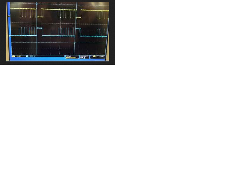
Q4: The output wave issue:
The actual output wave is different to "Figure 5. BD Mode Modulation" of the datasheet. What is the reason?
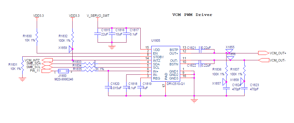
Please check the attachment. The yellow line is the OUT+ wave and the blue line is the OUT- wave. The customer's schematic is also in the attachment. The customer uses the single-ended output.
Best Wishes,
Mickey Zhang
Asia Customer Support Center
Texas Instruments

