This thread has been locked.

If you have a related question, please click the "Ask a related question" button in the top right corner. The newly created question will be automatically linked to this question.

DRV8308: DRV8308 consumes 130mA at plug in

Part Number: DRV8308

Hi-

I’ve been working with the DRV8308 EVM for a while and finally got some proto boards back for integrating it into my own design. However I’m seeing a problem where when I apply 24V at the input, the chip takes 130mA and gets very hot. This is on the initial power-on, so I haven’t loaded it with any settings or even tried sending a signal from the microcontroller beyond setting the ENABLE pin to 0V.

I’ve verified that it is the motor drive consuming the power but cutting the +24V trace to the 8308 and everything else runs as expected. I haven’t connected the motors yet at all in any of my testing. I have also gotten the same results with a board that doesn’t have the drive FETs populated.

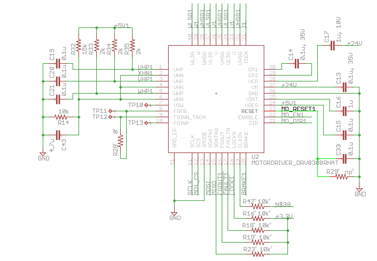
I’ve attached my schematic, and here is a description of all of the pins, where they are connected, and their value. Did I connect something incorrectly? Is there something I’m missing?

VSW: 0V

VREG: ~1V

ENABLE: 0V

FaultN: 3.3V (pulled up to digital VCC)

SCLK, SCS, SDATAI, SDATAO, FGOUT, FAULTN, LOCKN, BRAKE, DIR, ENABLE, and RESET all go to the microcontroller with pullups as shown in the schematic

Thanks!

  • Hi Dave,

    The schematic appears to be good.

    Do you have multiple boards to try?
    Have you measured the resistance between VM and GND on a previously untested board?
    Have you verified the layout matches the schematic
    Can you slowly ramp your power supply on a second board?
    Is it possible there is a voltage spike greater than the absolute maximum when powering up?
  • Thanks for the speedy reply Rick! I'm going to run those tests you suggested and see if there are unexpected voltage spikes above the max input V,  and change the 8308 in order to test the resistance from VM to GND as well as slowly ramp up the supply. Is there a figure that I should expect to see for resistance from VM to GND that would be good/bad?

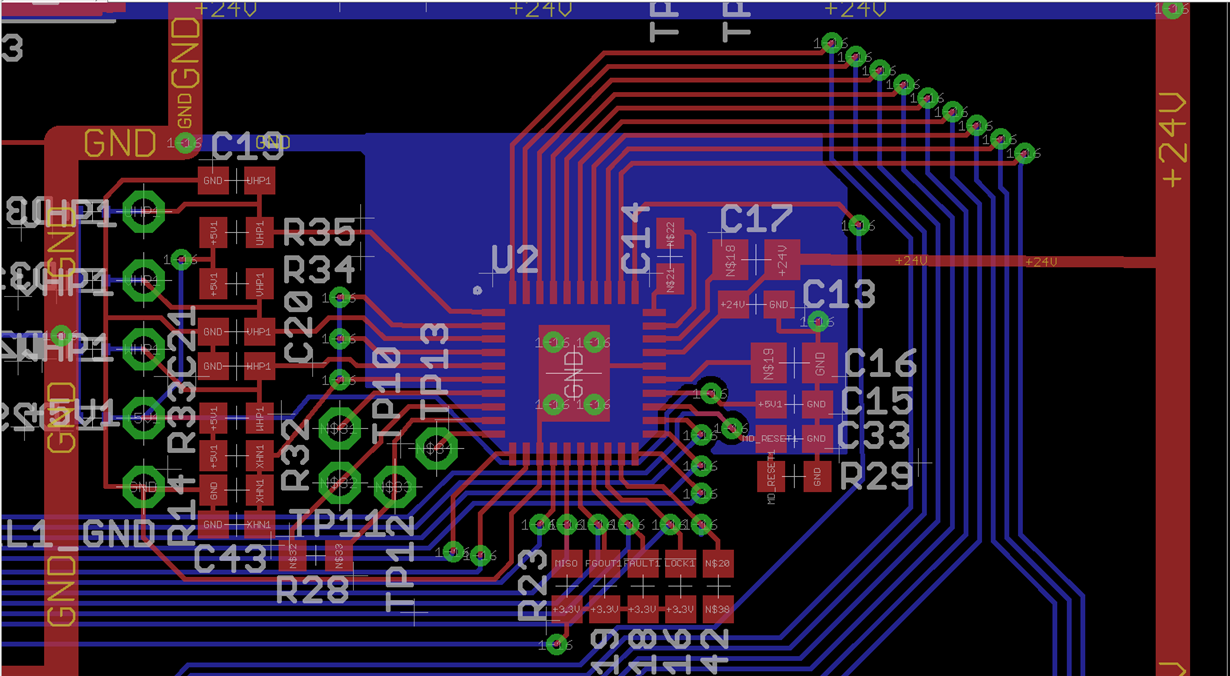
    I verified that my layout does connect the pins as expected. I've attached an image below so you can see what I've got going. Red = top copper, Blue = bottom copper. The partial pour on the bottom layer under the chip is connected to GND.

  • Quick Update based on testing from a failing unit:
    I put a scope probe across C13 with a small spring ground clip to make sure the turn-on voltage is safe and I got the attached scope shot. I did the same while using the 8303's pin 13 as ground and got the same result. I'm driving the system with 18V for now (representative of the input from a low battery).

    I also slowly ramped up the voltage (turning the knob of my voltage supply manually from 0-18V over a period of about 5 seconds) and found that the current went up to ~130mA right about when the input voltage reached 5V.

    I'm going to change the 8308 on this board, measure the resistance to VM, and slowly ramp up the voltage from 0 to 18V and see what happens.

    Thanks again,
    Dave
  • Complete update:

    I tested the resistance of a few scenarios. I saw the resistance rising, which I assume is a result of the large amount of capacitance on the VM line (~70uF). I'm not sure what to make of it since the virgin IC has such a different result:

    1. Resistance from VM to GND on a board that is exhibiting the failure mode: Ramps from 20k - 2M over ~10sec
    2. Resistance from VM to GND on a board with the 8308 removed: Ramps from 20k - 2M over ~10 seconds
    3. Resistance from VM to GND with virgin 8308 IC on the board: Slowly ramps to 200k over ~20sec

    With a Virgin IC, disconnect the 3.3V power supply for the microcontroller, connect a scope to VM, and slowly ramp the voltage from 0-18V over ~10 seconds. Monitor input voltage and current.

    The system exhibited the failure mode, with the current rising to ~130mA once VM rises to ~5V and above.

    Boy, am I confused. Any ideas what could be wrong here?

    Thanks again!

  • Ahhh nuts -- I found the problem. I have an ESD protection diode on the 5V line since the user will be able to touch that lead on the external connector and it was populated with the wrong value and was sinking current. After removing all ESD diodes, the problem went away.

    Thanks for your help Rick!
  • Hi Dave,

    Glad to hear you found the problem.